Overview
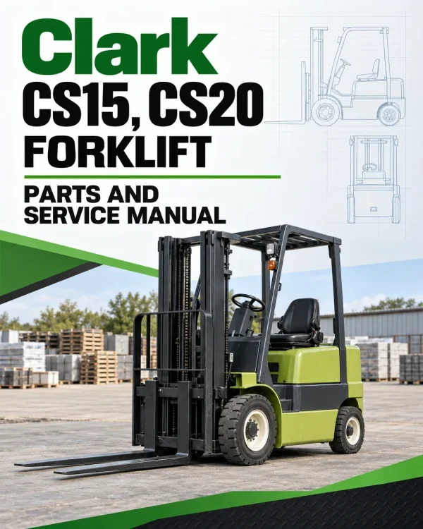
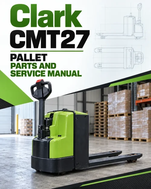
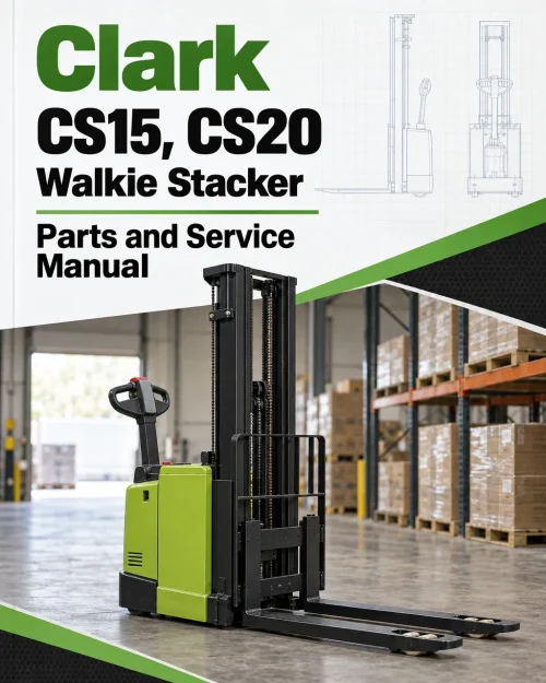
The Clark CS15, CS20 forklift parts and service manual provides a technical reference for parts identification, planned maintenance, inspection and servicing of the covered equipment. The documented contents address inspection and technical specifications, safety and planned maintenance, batteries and charging, brake and inching systems, and transmission and drive axle, with the individual sections and repair subjects organised in the table below.
The source outline also identifies lifting mechanisms and cylinders, parts assemblies and component replacement, and electrical wiring and instrumentation. Specific indexed topics include Battery Discharge Indicator (BDI) – Operation, BDI and Hourmeter, and BDI w/Lift Interlock. Use the applicable equipment identification and original chapter references when selecting inspection or repair procedures.
Table of Contents
Clark CS15, CS20 Manual
- 01. Receipt Inspection
- 02. Pre-Operation Instructions
- 03. Safety Information
- 04. Operating Instructions
- 05. Control System
- 06. Battery Discharge Indicator (BDI) – Operation
- 6.1 Hourmeter
- 6.2 BDI and Hourmeter
- 6.3 BDI w/Lift Interlock
- 07. Drive Unit & Brake
- 08. Mast and Carriage
- 09. Hydraulic Adjustments
- 9.1 Lifting Pressure
- 9.2 Lowering Speed:
- 10. Planned Maintenance
- 10.1 Lubrication Points
- 10.2 Lubrication Points
- 10.3 Lubrication Schedule
- 10.4 Battery Maintenance
- 10.5 Battery Cable Connections
- (for built-in battery / charger pack)
- 11. Trouble Shooting Guide
- 12. Heavy Duty Stacker – Parts Listings
- 12.1 General Assembly Parts List
- 12.2 Mast and Carriage Assembly – Single Stage
- 12.2.1 Cylinder Assembly – 3000 Single Stage
- 12.2.2 Cylinder Assembly – 4000 Single Stage
- 12.2.3 Crosshead Assembly – Single Stage
- 12.2.4 Chain Assembly – Single Stage
- 12.3 Mast and Carriage Assembly – 2 Stage
- 12.3.1 Lift Cylinder Assembly – Two Stage
- 12.3.2 Chain Assembly – 2 Stage
- 12.3.3 Crosshead Assembly – 2 Stage
- 12.4 Mast and Carriage Assembly – 2 Stage Full Free
- 12.4.1 Lift Cylinder Assembly – 2 Stage 130, 150" Full Free
- 12.4.2 Outboard Cylinder Assembly – 2 Stage 130, 150" Full Free
- 12.4.3 Chain Assembly – 2 Stage 130, 150" Lift Height
- 12.4.4 Crosshead Assembly – 2 Stage 130, 150" Lift Height
- 12.5 Mast and Carriage Assembly – 3 Stage 160, 180" Lift
- 12.5.1 Cylinder Assembly – 3 Stage 160, 180" Lift Height
- 12.5.2 Chain Assembly – 3 Stage 160, 180" Lift Height
- 12.5.3 Crosshead Assembly – 3 Stage 160, 180" Lift
- 12.6 Mast and Carriage Assembly – 3 Stage 172" Lift Full Free
- 12.6.1 Chain Assembly – 3 Stage 172" Lift Full Free
- 12.6.2 Chain Assembly – 3 Stage 172" Lift Full Free
- 12.6.3 Crosshead Assembly – 3 Stage 172" Lift Full Free
- 12.6.4 Lift Cylinder Assembly – 3 Stage 172" Lift Full Free
- 12.6.5 Outboard Cylinder Assembly – 3 Stage 172" Lift Full Free
- 12.7 Left Straddle Assembly
- 12.8 Right Straddle Assembly
- 12.9 Right Straddle Assembly
- 12.10 Electric Drive Unit Assembly
- 12.11 Drive Unit Assembly – Electrical
- 12.11.1 Control Handle Assembly
- 12.11.2 Control Handle Head Assembly
- 12.11.3 Controller Panel Assembly
- 12.11.4 Drive Unit Wiring Kit
- 12.11.5 Drive Unit Column Assembly – Mechanical
- 12.11.6 Drive Unit Gearbox Assembly
- 12.11.7 Wiring Kit – Rear Battery Box Plate
- 12.12 Hydraulic Layout
- 13. Wiring/Hydraulic Schematic
- 13.1 Mechanical/Hydraulic Lift Control Schematic
- 13.2 Electric/Hydraulic Lift Control Schematic
Parts Identification and Assemblies — Lift Cylinder Repair
The document includes part-assembly or spare-parts references. Lift-cylinder repair or servicing is indexed.
Use the identified assembly when selecting replacement components. Choose the procedures appropriate to the installed lift assembly.
















Reviews
There are no reviews yet.