Overview
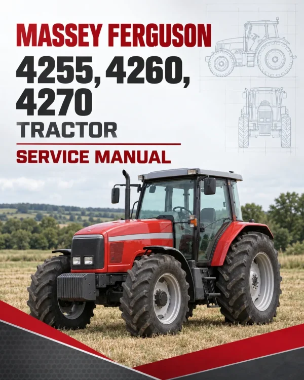
The Massey Ferguson 4255, 4260 and 4270 Tractor Workshop Service Manual provides technical information for servicing, troubleshooting and repairing these 4200 Series agricultural tractors. It includes equipment specifications, component identification, workshop procedures, system adjustments and repair references for major mechanical, hydraulic and electrical assemblies.
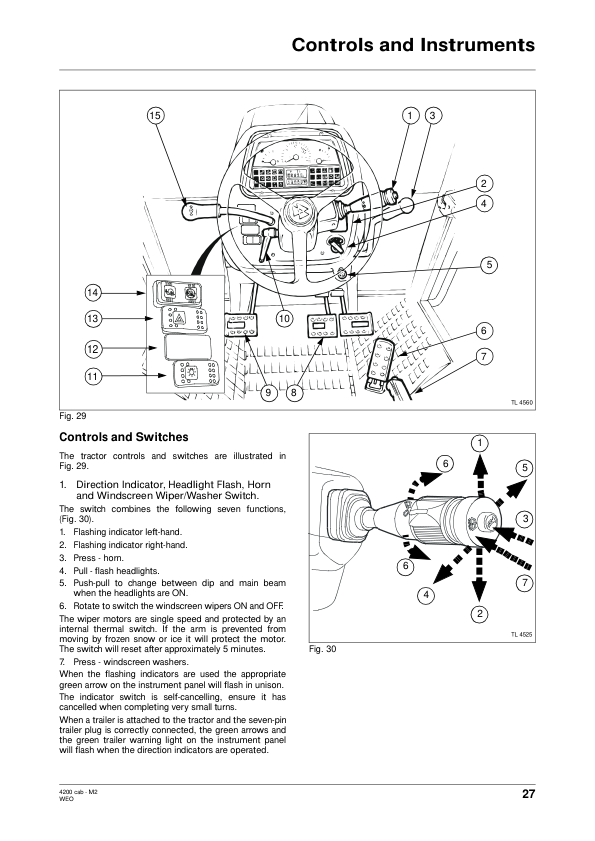
Coverage includes engine specifications, cooling and fuel systems, split-torque and oil-cooled clutches, multiple gearbox configurations, front and rear axles, braking systems, power take-off assemblies and hydraulic equipment. Additional chapters address electrical fault diagnosis, cab and footstep wiring diagrams, electronic lift controls, air conditioning, tractor separation and specialized service tools.
Safety: The introductory section contains workshop safety information and servicing guidance. Review the applicable instructions before tractor separation, mechanical adjustments or component removal.
Table of Contents
Massey Ferguson 4255, 4260, 4270 Manual
-
Introduction and Safety
- Introduction and Safety in the Workshop
- Tractor Specification
- Miscellaneous Data
- Servicing the Tractor
- Tractor Specification
-
Splitting the Tractor
- Splitting the Cab Tractor
- Splitting the Footstep Tractor
-
Engine
- Engine Specifications
- Cooling System
- Fuel System
- Air System
-
Clutch
- Split Torque Clutch
- Oil Cooled Clutch
-
Gearbox
- 12 x 12 Shuttle Gearbox
- 12 x 12 Creeper Gearbox
- 18 x 6 Speedshift Gearbox
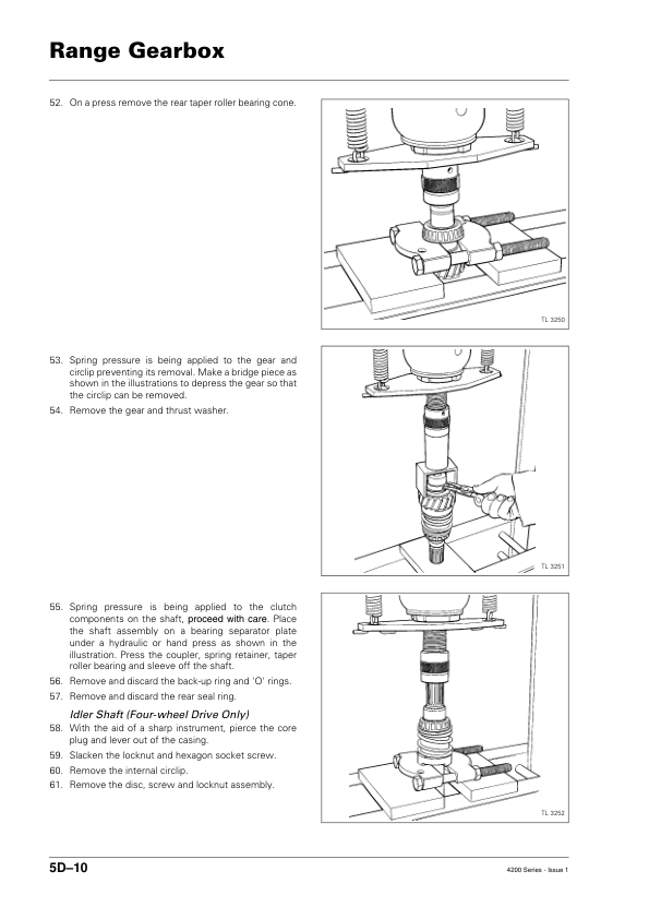
- Range Gearbox
- Four-Wheel Drive Shaft
- 8 x 8 Shuttle Gearbox
- 12 x 4 Manual Gearbox
- Four-Wheel Drive Gearbox
- Power Shuttle Gearbox
-
Rear Axle
- Brakes
- Crownwheel and Pinion
- Rear Axle
- Drawbar and Linkage
- Wheels and Tyres
-
Power Take-Off
- Single-Speed Power Take-Off
- Two-Speed Power Take-Off
- Front Power Take-Off
-
Front Axle
- Two-Wheel Drive Front Axle – 1
- Two-Wheel Drive Front Axle – 2
- Four-Wheel Drive Front Axle
- Four-Wheel Drive Front Portal Axle
-
Hydraulics
- Lift Hydraulics
- Hydraulic Steering
- Auxiliary Hydraulics
-
Electrical System
- Electrical System
- Cab Wiring Diagrams
- Footstep Wiring Diagrams
-
Electronics
- Speedometer and Performance Monitor
- Electronic Lift Control
- Electronic Lift Control (Two Lever)
-
Cab and Sheet Metal
- Cab
- Sheet Metal
- Air Conditioning
-
Accessories
- Accessories – Front Power Take-Off and Front Three-Point Linkage
- Accessories – Third and Fourth Control Valve Sections
- Accessories – Reverse Bleeper and Light
-
Service Tools
Transmission and Equipment Configuration Reference
The workshop documentation distinguishes several gearbox arrangements, including 12×12 shuttle and creeper, 18×6 Speedshift, 8×8 shuttle, 12×4 manual and Power Shuttle systems. Clutch information is also separated into split-torque and oil-cooled designs. Identify the installed transmission and clutch arrangement before selecting the corresponding servicing procedures, specifications or adjustments.
Front axle coverage includes two-wheel-drive, four-wheel-drive and portal axle configurations, while the power take-off chapters distinguish single-speed, two-speed and front PTO equipment. Separate electrical diagrams are provided for cab and footstep tractor arrangements. The hydraulic and electronic sections include lift control, steering, auxiliary circuits and electronic lift control references relevant to system diagnosis and repair.

















Reviews
There are no reviews yet.