Overview
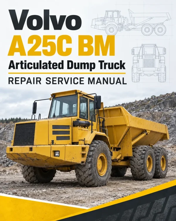
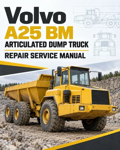
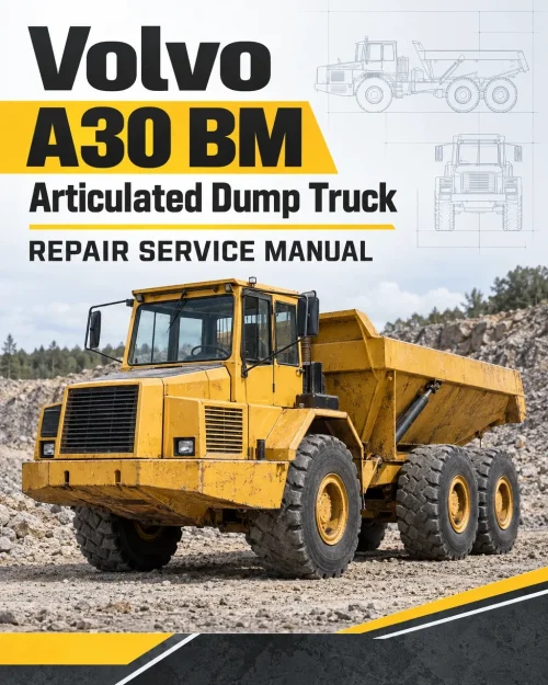
The Volvo A25C BM Articulated Dump Truck Service Repair Manual organizes service information for workshop maintenance, fault investigation and component repairs. Its service groups address power transmission, braking equipment, steering components, and working and servo hydraulics.
The service topics include differential-lock controls, transfer gearbox components, parking-brake components, compressed-air braking, and crankshaft and connecting-rod components.
Table of Contents
Volvo A25C BM Manual
-
01. General
- Specifications — Product Identification Numbers (PIN) and serial number locations (type plates)
- Standard Time
- Tool
-
02. Standard Parts, Service
- Lubricant; Fuel; Other Fluid
- Service — Maintenance
- Safety equipment, without own function group — On completion of service work or when the machine is parked for a longer period of time
-
03. Engine with Mounting and Equipment
- General, engine installation and its function
- Engine — General, common info about 211 – 218
- Engine — Cylinder head
- Engine — Cylinder block with crankcase ventilation
- Engine — Cylinder liner; piston
- Engine — Valve mechanism
- Engine transmission; camshaft
- Engine — Crank shaft; connecting rod; vibration damper; fly wheel
- Engine — Oil sump, dipstick incl.
- Engine mounting
- Lubricating System — General, common info about 221 – 224
- Lubricating System — Oil pump; line
- Lubricating System — Oil filter; filter housing
- Fuel System — General (common info about 233 – 238)
- Fuel System — Fuel pump; filter; strainer
- Fuel System — Fuel tank; fuel filling pump
- Fuel System — Injection pump; regulator; pump companion
- Fuel System — Injector; delivery pipe
- Inlet System; Exhaust System — Inlet manifold; exhaust manifold
- Inlet System; Exhaust System — Turbo charger
- Inlet System; Exhaust System — Air cleaner with connections; air pre-heater
- Inlet System; Exhaust System — Charge air cooler with connections
- Cooling System — General, common info about 261 – 269
- Cooling System — Radiator, mounting and connections included
- Cooling System — Coolant pump; thermostat
- Cooling System — Fan; fan shroud; fan coupling
- Engine Control — Revs control, foot operated
-
04. Elec. System; Warning System; Information System; Instruments
- Comprehensive info, electrical system
- Battery; Energy Storage System; Mounting Parts — Battery
- Alternator; Charging; Electric Motor; Electric Drives — Alternator inclusive drive
- Alternator; Charging; Electric Motor; Electric Drives — Charging; converter
- Starting System — Starter motor inclusive solenoid
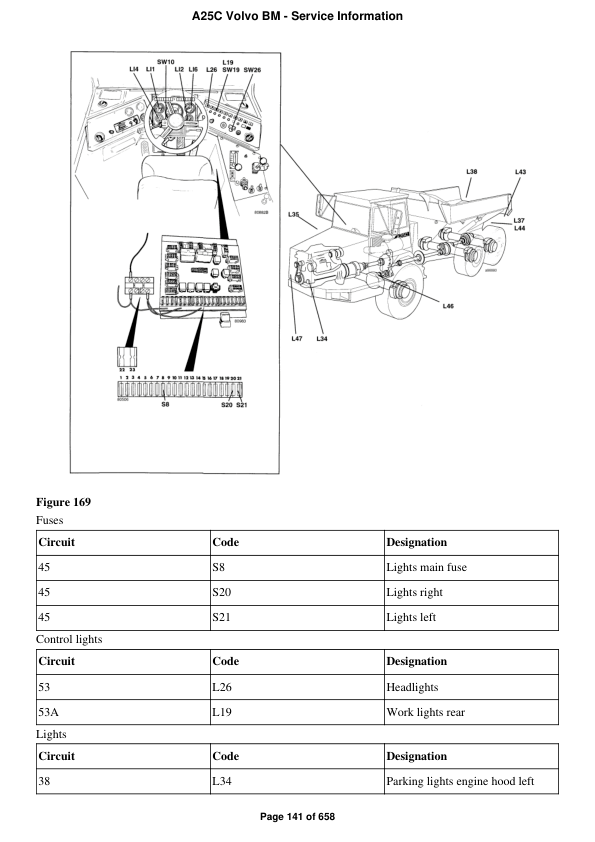
- Lighting — General, common info about 351 – 356
- Lighting — Bulbs
- Lighting, front, including parking light and day running light
- Other Electrical Equipment — General, common info about 361 – 367
- Other Electrical Equipment — Switch; connector
- Other Electrical Equipment — Electronic standard components
- Cable; Fuse; Relay — Electrical distribution box; fuse box; junction box
- Instrument; Sensor; Warning and Information System — General, common info about 383 – 387
- Instrument; Sensor; Warning and Information System — Sender, monitoring system
- Instrument; Sensor; Warning and Information System — Warning/information unit, display unit
- Miscellaneous — General, common info about 393 – 395
-
05. Power Transmission
- General, common info about 410 – 436
- Clutch; Torque Converter — Hydrodynamic coupling, torque converter
- Transmission, hydraulic control
- Gearbox — Distributing gearbox
- Propeller shaft, complete
- Front Axle; Rear Axle — General, common info about 461 – 468
- Front Axle; Rear Axle — Front axle
- Front Axle; Rear Axle — Rear axle 1
- Front Axle; Rear Axle — Rear axle 2
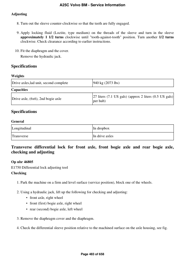
- Front Axle; Rear Axle — Differential lock, with control — Transverse differential lock for front axle, front bogie axle and rear bogie axle, checking and adjusting
- Power take off
- Power take off, between engine and gearbox (ART) — Power take-off in flywheel housing, reconditioning(rear engine transmission)
-
06. Brake
- Comprehensive info about brakes
- Wheel Brake — General, common info about 511 – 519
- Wheel Brake — Front wheel brake, dry brake
- Hydraulic Brake System — General, common info about 520 – 522
- Parking Brake — General, common info about 551 – 554
- Parking Brake — Brake control, mechanical
- Compressed-air Brake — General, common info about 561 – 565
- Compressed-air Brake — Compressor; regulator; antifreeze unit
- Compressed-air Brake — Compressed-air tank, with mounting
- Compressed-air Brake — Valves, compressed-air
- Retarder
-
07. Steering
- Comprehensive info, steering
- General, common info about 641 – 647
- Steering gear
- Steering arm; steering linkage; track rod
- Hydraulic equipment — Steering system, checking and adjusting operating pressure (Pump 1 and 2)
- Hydraulic equipment — Steering valve neutral position and valve slide (spool) axial clearance, checking
-
08. Frame; Springs; Damping; Axle Suspension; Wheel/track Unit
- Frame — General, common info about 711 – 718
- Frame, complete
- Frame components
- Suspension — Hollow rubber spring, bump stop
- Frame Link — General, frame link complete
- Frame Link — Bearings
- Frame link grader
- Axle Suspension — Movable member system, front/rear
- Axle Suspension — Bogie suspension
- Wheels; Tracks; Tyre; Hub; Drum — Wheel
-
09. Machinery House; Cab; Exterior Trim Parts Anywhere
- Cab, Naked; Canopy
- Trim Part, Outside; Glass; Sealing Moulding — Glass; sealing moulding
- Cab Interior/upholstery — Driver’s seat, complete; instructor’s seat
- Air Conditioning Unit — General, common info about 872 – 877
- Air Conditioning Unit — Cooling unit
- Interior Equipment — General, common info about 881 – 884
-
10. Hydraulic System; Digging/ Handling/ Grading Equipm.; Misc. Equip.
- Working Hydraulics; Servo Hydraulics — Tank; line; oil cooling; filter; breather; filling pump
- Working Hydraulics; Servo Hydraulics — Working hydraulics
- Working Hydraulics; Servo Hydraulics — Pump, working hydraulics
- Working Hydraulics; Servo Hydraulics — Other hydraulic equipment
- Load Carrier — Hauler/platform body, incl. tipping cylinder; heating; tail gate
Steering Pump Pressure Checks and Steering Valve Spool Clearance
The associated entries are “Steering system, checking and adjusting operating pressure (Pump 1 and 2)” and “Steering valve neutral position and valve slide (spool) axial clearance, checking”.
Pressure-check entries and component-removal entries serve different tasks; match the procedure title to the intended work.






















Reviews
There are no reviews yet.