Overview
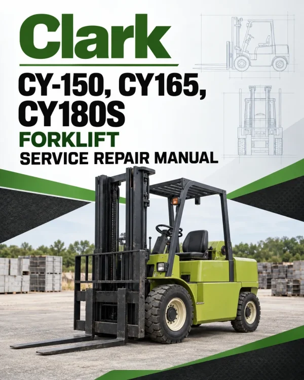
The Clark CY-150, CY165, CY180S forklift service repair manual provides a technical reference for maintenance, troubleshooting, inspection and component servicing of the covered equipment. The documented contents address inspection and technical specifications, brake and inching systems, lifting mechanisms and cylinders, cooling and intake systems, and transmission and drive axle, with the individual sections and repair subjects organised in the table below.
The source outline also identifies electrical wiring and instrumentation, batteries and charging, engine and fuel systems, and hydraulic pumps and valves. Specific indexed topics include Section I – Brake System, Bleeding Brakes, and Brake Adjustment. Use the applicable equipment identification and original chapter references when selecting inspection or repair procedures.
Table of Contents
Clark CY-150, CY165, CY180S Manual
- 01. Introduction
- Lube Chart
- Operation
- Service Check Sheets
- Specifications
- 02. Section I – Brake System
- Bleeding Brakes
- Brake Adjustment
- Brake Pedal Adjustment
- Brake Shoes
- Hand Brake
- Hydrovac
- Master Cylinder
- Wheel Cylinder
- 03. Section Ii – Torque Converter
- Description
- Operation
- Overhaul
- Reassembly
- Trouble Shooting Guide
- 04. Section Iii – Cooling System
- Description
- Fan Assembly
- Thermostat
- Water Pump
- 05. Section Iv – Drive Axle and Differential
- Backlash Adjustment
- Cleaning and Inspection
- Differential and Carrier
- Disassembly
- Maintenance
- Pinion
- Planet Spider
- Reassembly
- Trouble Shooting Guide
- 06. Section V – Electrical System
- Battery
- Distributor
- Generator
- Ignition Coil
- Solenoid
- Spark Plugs
- Specifications
- Starting Motor
- Trouble Shooting Guide
- Voltage Regulator
- 07. Section Vi – Engine
- Camshaft
- Compression
- Connecting Rods
- Connecting Rod Bearings
- Crankshaft
- Cylinder Head
- Flywheel
- Governor
- Main Bearings
- Oil Pressure
- Piston, Rings and Pins
- Specifications
- Trouble Shooting Guide
- Valves
- 08. Section Vii – Fuel System
- Carburetor
- Fuel Pump
- Fuel Tank
- Metering Valve
- Trouble Shooting Guide
- 09. Section Viii – Hydraulic System
- Flow Control Valve
- Hydraulic Oil
- Leakage Tests
- Pump, Main
- Steering Booster Pump
- Tilt Cylinder
- Tilt Lock Valve
- Upright
- Valve, Main
- 10. Section Ix – Steering System
- Axle
- Booster Cylinder
- Steering Gear
- 11. Section X – Transmission
- Description
- Disassembly
- Lubrication
- Operation
- Overhaul
- Reassembly
Governor Overhaul — Torque Converter Servicing
Governor adjustment or overhaul is listed among engine procedures. The contents separately name torque-converter or converter-pump work.
Identify the installed powerplant and transmission separately before using component specifications or overhaul instructions.
















Reviews
There are no reviews yet.