Overview
The Kubota KX91-3 and KX101-3 Excavator Workshop Service Manual provides technical information for inspection, maintenance, troubleshooting and component repair of these Kubota compact excavators. Its General and Machine Body chapters cover identification, workshop safety, bucket and front attachment components, swivel frame, track assemblies and operator controls. Engine references address fuel injection pump installation, radiator fan components and related service data, while the Hydraulic and Electrical System chapters detail component operation, testing and repair.
The workshop documentation includes variable-displacement hydraulic pump data, arm regeneration and boom anti-drift circuits, pilot and travel motor servicing, pressure and flow tests, electrical wiring diagrams and Auto Idle (AI) diagnostics. Instructions distinguish regional configurations, including KE/KDG/KUK and KTC/KCL/KTA versions, and standard versus AI electrical systems. An additional Optional Units chapter documents KTA hydraulic testing and selected KTC equipment kits, including canopy, cabin, third-line hydraulic and steel-crawler installations.
Safety: Review the servicing, disassembly and reassembly precautions before starting work. The General chapter identifies critical safety and functional processes, and requires post-assembly checks for unusual noise, vibration, safety decal and wiring harness clamp positions, and hydraulic oil level with the machine front in the specified posture.
Important Information: Certain hydraulic circuits, cylinder procedures and electrical diagrams apply only to the stated regional or Auto Idle configurations. KTA service-port and breaker tests and KTC installation kits are identified separately; do not assume every optional unit is fitted to both excavator models.
Table of Contents
Kubota KX91-3, KX101-3 Manual
-
01. General Information and Safety
- Machine Body and Engine Identification Marks
- Workshop Safety Measures Before and During Service
- Protective Equipment, Cranes and Team Operations
- Cleaning, Inspection and Preparation Before Disassembly
- Disassembly and Reassembly Precautions
- Essential Adhesives and Critical Safety/Functional Processes
- Post-Assembly Checks — Noise, Vibration and Safety Decals
- Wiring Harness Clamp Positions and Hydraulic Oil Level Checks
- Service Fundamentals — O-Rings, Oil Seals, Circlips and Roll Pins
- Hydraulic Piping and Hose Handling Precautions
- Hose Clamps, Pipe Connections and Joint Body Tightening Torques
- Fastener Types, Materials and Bolt/Nut Tightening Torques
-
02. Machine Body — Mechanism and Servicing
- Front Attachment Greasing Points and Bucket Interchangeability
- Swivel Frame, Swivel Bearing and Accelerator Linkage
- Standard Accelerator Lever — Engine Speed and Operating Force
- Auto Idle Accelerator Linkage — Lever, Motor and Engine Connections
- Track Frame, Tension Spring and Track Tension Adjustment
- Rubber-to-Iron Track Conversion Components
- Grease Tension Cylinder, Drive Sprocket and Track Construction
- Machine Weights and Specifications — Regional Versions
- Control Lever Strokes, Operating Forces and Component Dimensions
- Front Pins, Bucket, Track Rollers, Idlers, Sprockets and Dozer Dimensions
- Bucket, Bucket Tooth and Side Cutter Replacement
- Dust Seal Orientation and Swing-Bracket Thrust Collar Installation
- Swing-Bracket Pins, Bushings and Support Bushing Replacement
- Swing-Bracket Looseness Measurement
- Front Attachment Fixing Pin Bolts, Hoses and Clamps
- Upper Structure Swivel Bearing
- Travel Lever, Travel Lever Lock and Neutral-Position Adjustment
- Accelerator Lever Adjustment — Regional Versions
- Dozer Lever, Swing Pedal and Auxiliary Port Pedal
- Control Link Locations for Machine Operations
- Undercarriage Track Tension Device and Crawler Installation
- Track Roller and Upper Roller Installation
-
03. Engine — Mechanism and Service References
- Engine Technical Specifications, Features and Performance Curve
- Fuel Injection Pump Construction and Removal/Installation Precautions
- Engine Stop Lever Installation
- Radiator Fan, Coupling Flange and Fan Belt Tension
- Alternator, Temperature Sensor and Fan Flange Tightening Torques
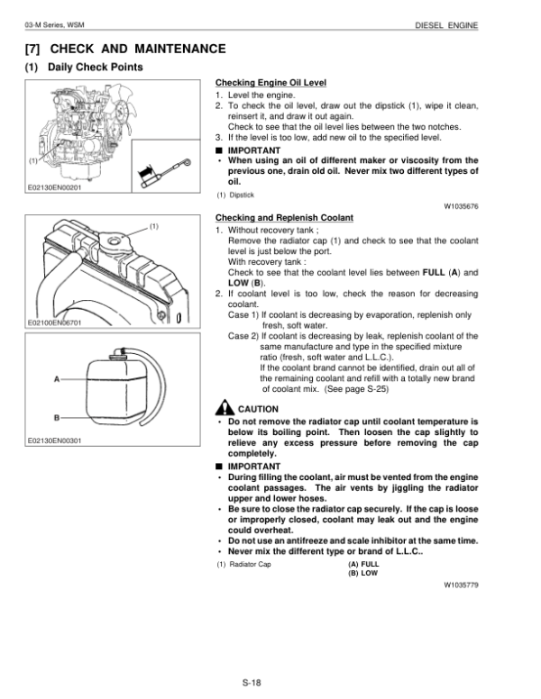
- Fuel Filter, Air Filter and Thermostat
- Additional Engine Workshop Service Manual Section
-
04. Hydraulic System — Mechanism, Testing and Repair
- Hydraulic System Features and Specifications
- Variable-Displacement Main Pump Structure and Performance Curves
- Main Control Valve Construction, Sectional Views and Circuit Diagrams
- Arm Regeneration Circuit — Arm Dump and Crowd
- Boom Lock/Anti-Drift Valve — Holding, Raising and Lowering
- Relief, Anti-Cavitation and Straight-Travel Circuits
- Pilot Valve Structure, Specifications and Control Diagrams
- Swivel Motor, Negative Brake and Brake Release Operation
- Swivel Motor Shockless, Make-Up and Relief Valves
- Rotary Joint (Swivel Joint)
- Travel Motor Construction, Counterbalance Valve and Speed-Change Spool
- Travel Motor Piston Operation and Shockless Valve
- Change Valve with Accumulator — EU Version
- Pilot Filter, Return Filter and Suction Strainer
- Hydraulic Circuit Diagrams — KX91-3 and KX101-3 European Versions
- Hydraulic Circuits — KX91-3 KTC/KCL and KTA Versions
- Hydraulic Component Layouts and KX91-3 KTA Service-Port Flow Reference
- Hydraulic Troubleshooting — Common, Attachment, Swivel and Travel Circuits
- Relief Valve Pressure, Pump and Cylinder Service Specifications
- Swivel and Travel Performance Specifications — Regional Versions
- Hydraulic Test Instruments and Special Tools
- Main Pump Flow and Primary/Secondary Pilot Pressure Testing
- Main Relief, Overload Relief and Swivel Brake Pressure Testing
- Travel and Swivel Motor Drain Flow Measurement
- Swivel and Travel Motor Block Performance Tests
- Boom, Arm, Bucket, Swing and Dozer Cylinder Speed Tests
- Straight-Travel, Swivel-Speed and Travel-Speed Performance Tests
- Cylinder Natural Fall, Control Lever Force and Stroke Checks
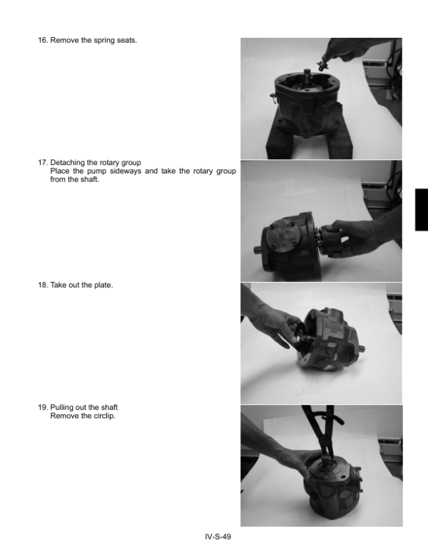
- Pump Coupling Flange, Main Pump and Adaptor Disassembly/Assembly
- Control Valve and Relief Valve Disassembly/Assembly
- Pilot Valve and Hose Servicing — Regional Versions
- Swivel Motor Disassembly/Assembly — KTC/KCL/KTA Versions
- Travel Motor Disassembly/Assembly — KTC/KCL/KTA Versions
- Rotary Joint Disassembly, Assembly and Adaptor Installation
- Hydraulic Cylinder Disassembly/Assembly — Regional Versions
- TPSS Valve — KTC/KCL/KTA Versions Only
- Pilot, Delivery, Return and Drain Hoses and Rotary Joint Connections
-
05. Electrical System — Circuits and Diagnostics
- Electrical Components, Wiring Harnesses and Coupler Layout
- Standard-Version Battery, Safety Relay and Auto-Release Circuits
- Standard Auto-Glow Circuit and Engine Stop Solenoid
- Engine Oil Pressure, Horn, Cab and Working Lamp Circuits
- Heater and High-Speed Travel Control Circuits
- Auto Idle (AI) Motor Control and Accelerator Response
- AI Starter Lock, Auto-Release and Self-Holding Relay Circuits
- AI Coolant Temperature, Meter Panel and Controller Circuits
- Key Switch, Safety Lever Lock and Travel High/Low Switches
- Engine Speed, Accelerator, Governor and AI Pressure Sensors
- Standard Electrical and Functional Circuit Diagrams
- KX101-3 EU Auto Idle Circuit Diagrams and Harness Couplers
- Cab Electrical Diagram — Regional Versions
- Electrical Fault Diagnosis — Connectors, Switches, Fuses and Relays
- Working Light and Safety Lever Lock Troubleshooting
- Engine Oil Pressure, Temperature and Fuel Sensor Fault Diagnosis
- Engine Stop Solenoid, Charging, Glow and Auto-Release Fault Diagnosis
- Auto Idle Pressure Switch, Accelerator/Governor and Motor Testing
- AI Controller Diagnosis Using a Circuit Tester
- Auto Idle Lamp Error Identification, Service and Setup Modes
-
06. Optional Units — Regional Equipment and Kits
- KX91-3 KTA Service-Port Flow Test Method and Performance Data
- KTA Hydraulic Breaker Performance Tests and Service-Port Flow
- KTC Canopy Kit Parts and Installation Instructions
- KTC Working Light Kit Installation References
- KTC Cabin Kit Parts and Installation Instructions
- Heat Insulator and Spark-Arresting Muffler Kit Installation
- Spark-Arrester Muffler Maintenance — 250 Service Hours
- Auxiliary Relief Valve and Cylinder Mounting Bracket Kit
- Thumb Installation Safety and Welding Instructions
- Third-Line Hydraulic Kit Installation and Inspection
- Steel Crawler Conversion — Rubber Track Removal and Spring Adjustment
- Steel Track Installation and Crawler Adjustment
Hydraulic Testing, Auto Idle Diagnostics and Optional Equipment
The Hydraulic System chapters separate pump and valve operation from troubleshooting, pressure and flow testing, and component disassembly. The test references cover pilot and relief pressures, swivel brake pressure, travel and swivel motor drain measurements, cylinder operating speeds and straight-travel performance. Use the circuit diagram and service specifications corresponding to the machine’s regional configuration; the source also identifies a KX91-3 KTA-specific service-port flow reference.
The Electrical System documentation distinguishes standard wiring from the KX101-3 European Auto Idle arrangement, including AI motor control, sensor testing, controller diagnostics and lamp-based error identification. The optional-unit instructions cover equipment kits and hydraulic tests rather than establishing that those accessories are installed on every machine. When repairing bucket and swing-bracket joints, consult the relevant dust-seal, bushing, O-ring and assembly instructions instead of assuming that sealing parts or fitting directions are interchangeable.




























Reviews
There are no reviews yet.