Overview
The Kubota U35 and U35-3 excavator workshop service manual provides detailed technical information for machine maintenance, troubleshooting, inspection and repair. It covers essential service procedures, mechanical components, hydraulic operations and electrical systems, with specifications and diagnostic references for the applicable machine versions.
The documentation includes machine body servicing, engine components, hydraulic circuit operation, pressure and performance testing, electrical wiring diagrams and troubleshooting procedures. Detailed sections also address component disassembly and reassembly, undercarriage maintenance, control adjustments and auto-idle system diagnostics.
Table of Contents
Kubota U35, U35-3 Manual
- 01. General
- Machine body and engine identification marks
- Safety precautions for servicing, disassembly and reassembly
- Safety measures before starting work, including work clothing, tools and workshop preparation
- Safety measures during work, including protective equipment, teamwork and lifting operations
- Preparation and inspection procedures before disassembly
- Precautions during component disassembly and reassembly
- Essential adhesives, important safety processes and critical functional processes
- Important inspection items after reassembly
- Maintenance intervals for KTC, KCL and KTA versions
- Maintenance intervals for European KE, KDG and KUK versions
- Hydraulic oil inspection intervals for machines equipped with hydraulic breakers
- Water and oil quantities, recommended lubricants and filters
- Tightening torque specifications for hoses, joints, clamps, piping, bolts and nuts
- Bolt types, materials and washer-equipped elbow fittings
- Machine quality specifications
- 02. Machine Body
- Front attachment mechanism, greasing points and component interchangeability
- Bucket and arm interchangeability
- Dust seal installation direction
- Bushing and thrust collar installation on the swing bracket
- Pin, bushing and shim installation procedures for the U35
- Bucket pin, bushing and shim installation
- Local bucket installation for the U35
- Machine weight specifications for European and KTC, KCL, KTA versions
- Machine specifications and operating characteristics
- Control lever stroke and operating force specifications
- Component dimensions for front pins, buckets, tracks, rollers, idlers, sprockets and dozers
- Component weight specifications
- Front attachment parts identification
- Upper structure and swivel frame specifications for the U35 and U35-3
- Swivel bearing construction and installation
- Travel lever mechanism, adjustments and locking system
- Travel lever neutral-position adjustment
- Accelerator lever mechanisms for standard and auto-idle versions
- Accelerator cable and engine-side connections
- Swing pedal and auxiliary port pedal
- Limit switch installation
- Hour meter and engine stop cables
- Cab installation for KTC, KCL and KTA versions
- Heater hose installation
- Cab glass replacement and adhesive application procedures
- Cab glass sealing, H-rubber replacement and glass repair
- Seat belt and weight installation
- Undercarriage tension spring preset length
- Components required for conversion from rubber tracks to iron tracks
- Track roller and upper roller installation
- Track tension adjustment and grease tension cylinder
- Drive sprocket, rubber track and iron track servicing
- 03. Engine
- Engine mounting components
- Radiator assembly and related components
- Muffler assembly
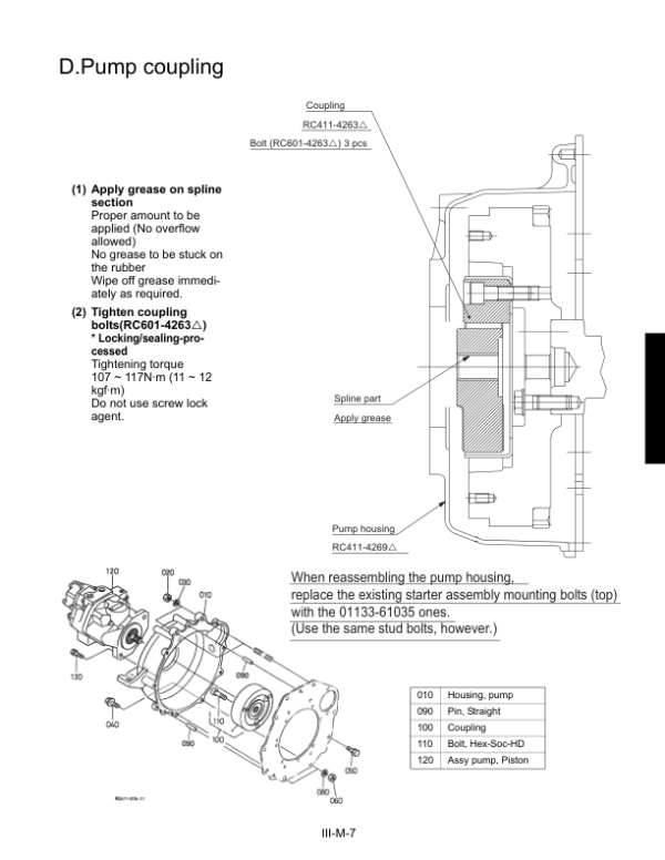
- Hydraulic pump coupling
- Fuel hose components and connections
- 04. Hydraulic System
- Hydraulic system features and operating principles
- Hydraulic system technical specifications
- Main hydraulic pump structure and specifications
- Variable-displacement pump performance curves
- Hydraulic control valve specifications
- Arm regeneration circuit operation during arm dumping and crowding
- Lock valve oil flow and boom operation
- Anti-drift valve operation, boom cylinder holding and boom raising and lowering functions
- Pilot valve structure and specifications for U35 KTC, KCL and U35-3 KTA versions
- Pilot valve control diagrams and European U35-3 pilot valve configuration
- Swivel motor construction and specifications
- Swivel motor negative brake operation and release
- Swivel motor make-up valve and shockless valve functions
- Swivel motor performance specifications and internal components
- Rotary joint and swivel joint mechanism
- Travel motor construction, relief valve and shockless piston
- Travel motor internal components and regional specifications
- Hydraulic circuit diagrams for European U35-3 versions
- Hydraulic circuit diagrams for U35 KTC, KCL and U35-3 KTA versions
- Hydraulic component arrangement for the U35 and U35-3
- Troubleshooting common hydraulic circuits
- Front attachment, swivel circuit and travel circuit troubleshooting
- Relief valve pressure settings and hydraulic pump service specifications
- Hydraulic cylinder specifications, operating speeds and natural fall measurements
- Swivel and travel performance specifications for different machine versions
- Hydraulic testing instruments and special service tools
- Main pump flow testing
- Primary and secondary pilot pressure testing
- Main relief valve and overload relief valve testing
- Swivel brake valve pressure testing
- Travel motor and swivel motor drain measurements
- Swivel motor and travel motor block performance testing
- Boom, arm, bucket, swing and dozer cylinder operating speed tests
- Swivel speed and travel speed testing
- Straight travel performance and cylinder natural fall testing
- Control lever operating force and lever stroke measurements
- Swivel motor disassembly and assembly for KTC, KCL and KTA versions
- Rotary joint disassembly, reassembly and internal component inspection
- Rotary joint seal and adapter installation procedures
- Rotary joint service jigs and technical drawings
- Hydraulic cylinder disassembly and reassembly for European versions
- Pilot hose service information
- 05. Electrical System
- Electrical component locations and wiring harness layout
- Electrical circuit diagrams
- Electrical wiring diagrams
- Electrical equipment specifications
- Wiring harness installation precautions
- Engine grounding and starter switch connections
- Main wiring harness installation and connector insertion
- Control box, engine and front attachment wiring harnesses
- General electrical troubleshooting and diagnostic procedures
- Switch, fuse, solenoid, relay, cable and wire testing
- Starter motor failure diagnosis
- Automatic release system malfunction diagnosis
- Electronic accelerator troubleshooting
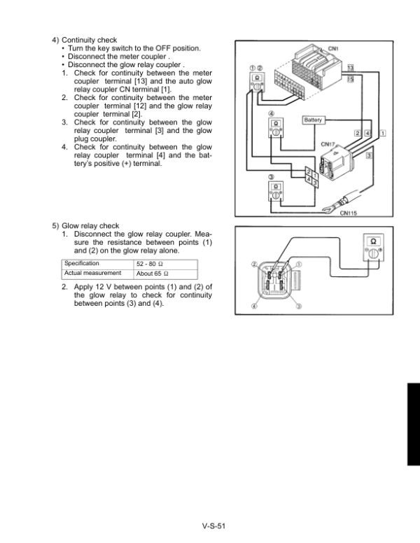
- Automatic glow system failure diagnosis
- Auto-idle system malfunction diagnosis
- Working lamp and safety lever lock circuit troubleshooting
- Engine oil pressure circuit troubleshooting
- Coolant temperature sensor and fuel sensor circuit diagnosis
- Engine stop solenoid troubleshooting
- Charging system fault diagnosis
- Automatic glow controller and automatic release controller troubleshooting
- Auto-idle pressure switch testing
- Governor sensor and auto-idle motor testing
- Engine speed sensor and automatic glow circuit testing
- Auto-idle controller diagnosis using a circuit tester
- Water temperature sensor circuit and related controller diagnostics
- Auto-idle error identification using indicator lamps
- Service mode entry and diagnostic menu operation
- Engine idling speed adjustment through service menus
- Auto-idle motor drive menu operation
- Setup mode access and configuration menus
- Error indication, fault identification and possible causes
Regional Specifications and Model Applicability
The documentation distinguishes between U35 and U35-3 configurations, with model-specific hydraulic circuits, pilot valve arrangements and service specifications. The U35 KTC and KCL versions are covered separately from the U35-3 European and KTA versions in relevant technical sections.
Maintenance schedules and component specifications also identify European KE, KDG and KUK configurations alongside KTC, KCL and KTA versions. Confirm the machine model and applicable version before using hydraulic diagrams, component dimensions, pressure settings or adjustment specifications.



























Reviews
There are no reviews yet.