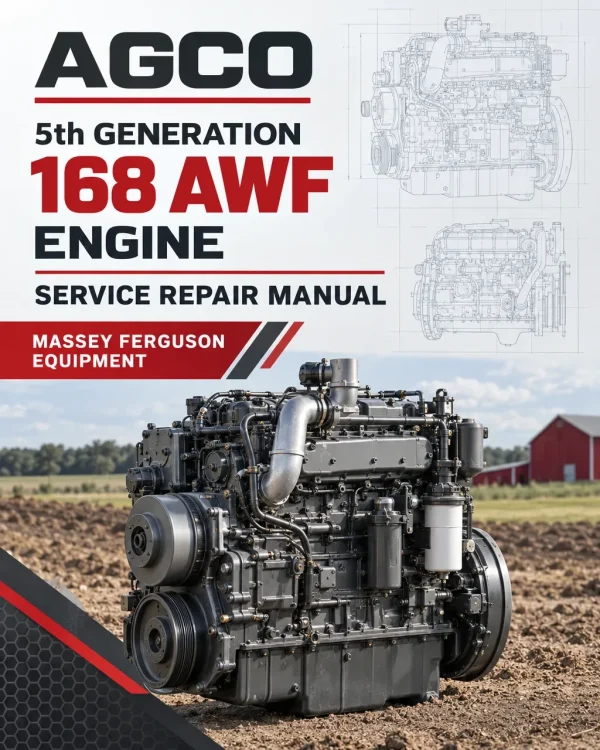
AGCO Power 168 AWF (5th Generation) Engine Workshop Manual

$22.00

What’s Included

Workshop Service Manual 96 Pages

Technical Details

Brand AGCO POWER
Models Covered 168 AWF
Machine Type Engine
Documentation Workshop Service Manual
Publication Number V837091047
Language English
Format PDF
SKU: 157750 Category:
Guaranteed Safe Checkout

‘

Overview

The AGCO Power 5th Generation 168 AWF Engine Workshop Service Manual provides technical information for inspecting, maintaining and repairing the AGCO Power 168 AWF diesel engine. Publication V837091047 is a 96-page manual covering the water-cooled, turbocharged, four-stroke engine with a 60-degree V-cylinder arrangement. The documentation includes engine construction, technical specifications, service tools, cylinder block components, timing gears, lubrication, cooling, fuel injection, air control, exhaust gas recirculation (EGR), selective catalytic reduction (SCR) and electronic engine management.

Workshop procedures include flywheel and crankshaft rear oil seal installation, oil pump servicing, thermostat replacement, coolant pump reconditioning, turbocharger removal and inspection, EGR cooler and actuator servicing, fuel pressure measurement, CRIN3 injector replacement and high-pressure fuel pump servicing. The manual also provides information on interstage charge air cooling (ICAC), fuel rail components, SCR system maintenance, electronic control unit replacement, engine wiring and diagnostic equipment. The 168 AWF belongs to the fifth-generation engine family described in the source as meeting Stage IV and Tier 4 Final emissions requirements.

Safety: Review the safety instructions and engine lifting information in the introductory chapter before carrying out workshop repair or maintenance operations.


Table of Contents

AGCO Power 168 AWF Manual

  • 01. Introduction and Engine Construction

    • Engine Safety Instructions
    • Information for Workshop Technicians
    • Engine Type Designations
    • Engine Serial Number Location
    • Engine Control Unit Identification and Markings
    • Engine Lifting Instructions
    • Engine Construction Overview
    • Principal Engine Dimensions and Technical Data
    • Fuel System Technical Data
    • Lubrication System Technical Data
    • Cooling System Technical Data
    • Electrical System Technical Data
    • SCR System Technical Data
    • Cylinder Block Construction
    • Flywheel Housing
    • Valve Mechanism
    • Cylinder Head
    • Crank Mechanism
    • Timing Gear Assembly
    • Lubrication System Construction
    • Engine Oil Pump
    • Oil Filter and Oil Cooler
    • Cooling System Construction
    • Coolant Pump and Thermostats
    • Air Control System
    • Two-Stage Turbocharging System
    • Interstage Charge Air Cooling (ICAC)
    • Throttle Valve
    • Exhaust Gas Recirculation (EGR) System
    • Fuel Injection System
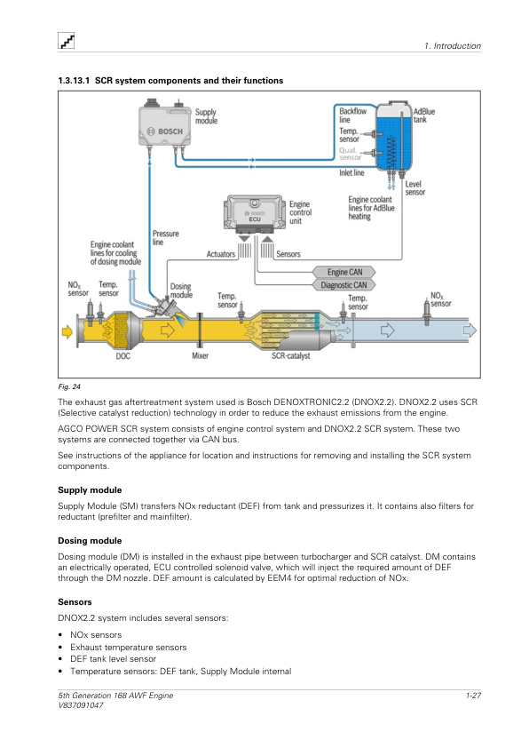
    • Selective Catalytic Reduction (SCR) System Overview
    • SCR Components and Their Functions
    • Electronic Engine Control System
    • Engine Electrical Wiring
    • Electronic Diagnostic Tools
    • EDT Diagnostic Terminal
    • Diagnostic Terminal Components
  • 02. Technical Specifications and Special Tools

    • Flywheel Technical Specifications
    • Lubrication System Specifications
    • Engine Oil Pump Specifications
    • Thermostat Technical Specifications
    • Turbocharger Technical Specifications
    • Engine Oil Quality Requirements
    • Coolant Quality Requirements
    • Fuel Quality Requirements
    • Engine Component Tightening Torques
    • Special Workshop Service Tools
    • Engine Lifting Tools
    • Timing Gear and Flywheel Housing Tools
    • Crank Mechanism Service Tools
    • Coolant Pump Service Tools
    • Fuel System Service Tools
    • Maintenance and Troubleshooting Tools
  • 03. Engine Maintenance and Workshop Repair Procedures

    • Flywheel Housing Installation
    • Crankshaft Rear Oil Seal Replacement
    • Flywheel Installation
    • Crankshaft Hub Installation
    • Timing Gear Assembly – Power Take-Off Reference
    • Oil Pressure Regulating Valve Inspection
    • Engine Oil Pump Removal
    • Engine Oil Pump Installation
    • Oil Sump Gasket Installation
    • Lubricating Oil Cooler Removal
    • Lubricating Oil Cooler Installation
    • Engine Oil Sump Capacity
    • Closed Crankcase Ventilation (CCV)
    • Closed Crankcase Ventilation Component Installation
    • Cooling System Maintenance
    • Thermostat Removal
    • Thermostat Testing
    • Thermostat Replacement
    • Coolant Pump Reconditioning
    • Cylinder Head Connection Component Installation
    • Air Control System Maintenance
    • Air Cleaner Inspection
    • Inlet and Exhaust Pipe Inspection
    • High-Pressure Turbocharger Actuator Removal
    • High-Pressure Turbocharger Actuator Installation
    • Low-Pressure Turbochargers and Mounting Bracket Removal
    • Low-Pressure Turbochargers and Mounting Bracket Installation
    • High-Pressure Turbocharger Removal
    • Turbocharger Inspection
    • High-Pressure Turbocharger Installation
    • EGR Cooler Removal
    • EGR Cooler Installation
    • EGR Actuator Removal
    • EGR Actuator Installation
    • EGR Link Rod
    • EGR Actuator Voltage Inspection
    • Interstage Charge Air Cooler (ICAC) Removal
    • Interstage Charge Air Cooler (ICAC) Installation
    • Fuel System Maintenance
    • Bleeding Air from the Fuel System
    • Fuel Feed Pressure Measurement
    • Fuel Injector Inspection
    • CRIN3 Fuel Injector Removal
    • CRIN3 Fuel Injector Installation
    • High-Pressure Fuel Pump Removal
    • High-Pressure Fuel Pump Installation
    • Common Rail Fuel System
    • Fuel Rail Removal
    • Fuel Rail Installation
    • Fuel Pressure Control Valve Removal
    • Fuel Pressure Control Valve Installation
    • Fuel Rail Pressure Sensor Removal
    • Fuel Rail Pressure Sensor Installation
    • Selective Catalytic Reduction (SCR) System Maintenance
    • SCR System Component Mounting
    • Electronic Engine Control System Maintenance
    • Electronic Control Unit (ECU) Replacement
    • Engine Control System Wiring Installation
    • Electrical Terminal Diagram
  • 04. Index

Wet Cylinder Liner Construction and Air-Handling Components

The AGCO Power 168 AWF engine uses wet, replaceable cylinder liners supported at the middle of the cylinder block. This arrangement helps reduce liner vibration while directing coolant circulation mainly toward the upper portion of the liners. Three O-ring seals fitted into grooves in the cylinder block seal the lower part of each liner, while the cylinder head gasket provides the upper seal. The camshafts are positioned within the cylinder block, with separate bearing sleeves at the camshaft bearing locations and a plug sealing the rear camshaft bore.

The engine’s air-handling arrangement includes two-stage turbocharging, dual interstage charge air cooling and dual exhaust gas recirculation systems. The maintenance instructions distinguish high-pressure and low-pressure turbocharger assemblies, EGR coolers and actuators, and ICAC components. These systems have separate removal, installation and inspection references, allowing technicians to locate the appropriate procedures for the relevant assembly.

Reviews

There are no reviews yet.

Only logged in customers who have purchased this product may leave a review.

AGCO 5th Generation 168 AWF Engine Manual
AGCO Power 168 AWF (5th Generation) Engine Workshop Manual

$22.00

Add to cart