Overview
The Massey Ferguson MF 3600 V, F, S and GE Series Tractor Workshop Service Repair Manual provides technical information for servicing, maintaining and repairing Massey Ferguson 3600 Series agricultural tractors. The documentation covers tractor specifications, engine-related components, mechanical and Common Rail fuel system configurations, transmission servicing, front axle assemblies, hydraulic systems, power take-off equipment, steering, braking, electrical circuits and major component removal.
Workshop coverage includes PowerShuttle and TRAX transmission components, 24+24 and 24+12 transmission-related hydraulic systems, clutch housings, front axle differential and planetary reduction assemblies, hydraulic distributors, rockshaft components and PTO control valves. Additional sections provide wiring harness diagrams, engine ECU electrical references, hydraulic circuit diagrams, troubleshooting procedures, component inspection, disassembly and reassembly, recommended lubricants, tightening specifications and special tools.
Models listed: 3615V, 3625V, 3635V, 3615F, 3625F, 3635F, 3645F, 3615S, 3625S, 3635S, 3645S, 3615GE, 3625GE, 3635GE, 3645GE, 3630V, 3640V, 3630F, 3640F, 3650F, 3660F, 3630S, 3640S, 3650S, 3660S, 3630GE, 3640GE, 3650GE, 3660GE.
Important Information: The workshop documentation includes different axle, transmission, mechanical injection and Common Rail configurations. The supplied bookmarks do not provide a model-by-model applicability list. Verify the tractor model, serial number and installed components before selecting the relevant service procedure.
Table of Contents
Massey Ferguson MF3600 V, F, S and GE Series Workshop Manual
-
01. Tractor – General Information and Specifications
- A. General Information
- A.2 Agreements and Definitions
- A.3 General Description
- B. Safety Instructions
- B.1 General Safety Recommendations
- B.2 Safety Symbols
- B.3 General Precautions
- C. General Specifications
- C.1 Product Identification
- C.2 General Description
- C.2.1 Steering Angle
- C.2.2 Steering Radius
- C.2.3 Travel Speed
- C.2.4 Battery
- C.2.5 Alternator
- C.3 Check Table
- C.4 Recommended Lubricants
-
02. Tractor – Disassembly and Assembly Operations
- D.1 Air Filter
- D.2 Air Filter – Common Rail Version
- D.3 Air Filter Line – Mechanical Injection
- D.4 Air Filter Line – Common Rail
- D.5 Battery
- D.6 Alternator
- D.7 Radiator – Mechanical Injection Engine
- D.8 Radiator – Common Rail Version
- D.9 Fan
- D.10 Exhaust Pipe – Mechanical Injection Engine
- D.11 Fan Belt
- D.12 Air Filter Assembly Replacement
- D.13 Air Filter Assembly Replacement – Common Rail
- D.14 Bonnet
- D.15 Front Weight
- D.16 Muffler – Mechanical Injection Engine
- D.17 Muffler – Common Rail Version
- D.18 Hydraulic Pump
- D.19 Starting Motor
- D.20 Engine Removal – Mechanical Injection Engine
- D.21 Engine Removal – Common Rail
- D.22 Front Axle 2WD
- D.23 Fuel Tank – Mechanical Injection Engine
- D.24 Fuel Tank – Common Rail
- D.25 Brake Cylinder
- D.26 Hand Brake
- D.27 Valves
- D.28 Rockshaft Valve
- D.29 Rear Wheels
- D.30 Auxiliary Distributors
- D.31 Oil Suction Strainer
- D.32 Oil Filter
- D.33 Side Auxiliary Distributors
- D.34 24+24 PowerShuttle Hydraulic Valve
- D.35 24+12 PowerShuttle Distributor
- D.36 GD PTO Valve
- D.37 Oil Filter Sensor
- D.38 Clutch Box – Mechanical Injection Engine
- D.39 Clutch Box – Common Rail
- D.40 Rockshaft
- D.41 Platform
- D.42 Steering Valve
- D.43 Brake Circuit Bleeding
- D.44 TRAX PowerShuttle Transmission
- D.45 24×12 TRAX
-
03. Tractor – Electrical, Hydraulic Systems and Troubleshooting
- E. Electrical System
- E.1 Main Electrical Components
- Electrical Diagrams – Mechanical Injection Version
- Electrical Diagrams – Common Rail Version
- F. Hydraulic System
- F.1 Hydraulic System Components – Mechanical Injection Engine
- Hydraulic Trailer Braking System Diagram
- Control Valve Options
- PowerShuttle Sync Hi-Lo 30-40 km/h Hydraulic Diagram
- 24+24 Power Hi-Lo Synchro Shuttle
- 12+12 Synchro Reverser and 24+24 Synchro Splitter
- Hydraulic Diagrams – Common Rail Version
- G. Troubleshooting
- G.1 General Troubleshooting
- G.2 Axle Problems
-
04. Axle – Service and Repair
- A. General Information
- A.1 Manual Use
- A.2 Information Property
- A.3 Agreements and Definitions
- A.4 General Description
- A.5 Recommendations for Repair Operations
- B. Safety Instructions
- C. General Specifications
- C.1 Intended Use
- C.2 Product Identification
- C.3 General Description
- C.4 Technical Features
- C.5 Maintenance
- C.6 Grease in Assembly
- C.7 Adhesives and Tightening Torques
- D. Disassembly and Assembly Operations
- D.1 Steering Cylinder Group
- D.2 Wheel Hub Group
- D.3 Wheel Hub Support Group
- D.4 Axle Beam Group
- D.5 Toe-In / Steering Angle
- D.6 Special Repair Operations
- E. Troubleshooting
- E.1 Troubleshooting
- E.2 Axle Problems and Diagnosis
- F. Special Tools
- G. Service Operations Time Schedule
-
05. Front Axle – Workshop Service Section 1
- General Information and Repair Recommendations
- Safety Instructions and Precautions
- Product Identification and Technical Features
- Maintenance and Oil Changes
- Grease, Adhesives and Tightening Torques
- D.1 Steering Cylinder Group
- D.2 Epicyclic Reduction Gear Group
- D.3 Wheel Hub Group
- D.4 Axle Beam Group
- D.5 Flange Group
- D.6 Trunnions Group
- D.7 Differential Support Group
- D.8 Differential Group
- D.9 Pinion Group
- D.10 Toe-In / Steering Angle
- D.11 Special Repair Operations
- D.12 Testing After Assembly
- Axle Troubleshooting and Diagnosis
- Special Tools
- Service Operations Time Schedule
-
06. Front Axle – Workshop Service Section 2
- General Information and Safety Instructions
- Product Identification and General Specifications
- Maintenance and Oil Changes
- Grease, Adhesives and Tightening Torques
- D.1 Steering Cylinder Group
- D.2 Epicyclic Reduction Gear Group
- D.3 Wheel Hub Group
- D.4 Axle Beam Group
- D.5 Flange Group
- D.6 Differential Support Group
- D.7 Differential Group
- D.8 Pinion Group
- D.9 Toe-In / Steering Angle
- D.10 Special Repair Operations
- D.11 Testing After Assembly
- Axle Troubleshooting and Diagnosis
- Special Tools
- Service Operations Time Schedule
-
07. Front Axle – Workshop Service Section 3
- General Information and Safety Instructions
- Product Identification and Technical Specifications
- Maintenance and Oil Changes
- Grease, Adhesives and Tightening Torques
- D.1 Steering Cylinder Group
- D.2 Wheel Hub Group
- D.3 Epicyclic Reduction Gear Group
- D.4 Axle Beam Group
- D.5 Flange Group
- D.6 Differential Support Group
- D.7 Differential Group
- D.8 Pinion Group
- D.9 Toe-In / Steering Angle
- D.10 Special Repair Operations
- D.11 Testing After Assembly
- Axle Troubleshooting and Diagnosis
- Special Tools
- Service Operations Time Schedule
-
08. Transmission – Workshop Service Section 1
- General Information
- Safety Instructions
- General Specifications
- Disassembly and Assembly Operations
- Special Tools
-
09. Transmission – Workshop Service Section 2
- Safety Instructions
- General Information
- General Specifications
- Disassembly and Assembly
- Special Tools
-
10. Electrical Wiring Diagrams
- W01 – Main Harness
- W02 – Engine Harness
- W03 – PowerShuttle Harness
- W04 – Cab Roof Harness
- W05 – Hood Harness
- W07 – PTO Harness
- W09 – Main Console Harness
- W09-2 – Console Harness
- W11-1 – ELC Console Harness
- W11-2 – ELC Remote Switches
- W11-3 – ELC Valves
- W18 – Pre-Heater Harness
- W27 – Engine ECU Supply
- Complete Electrical Diagram
PowerShuttle, Front Axle and Clutch Service
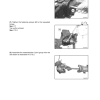
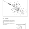
The Massey Ferguson MF3600 Series workshop documentation includes service procedures for engine-related components, PowerShuttle transmissions, clutch housings, hydraulic pumps, steering valves, braking systems and front axle assemblies. Its detailed axle repair references, electrical wiring diagrams, hydraulic schematics, troubleshooting information and special tool sections provide practical technical support for servicing compatible MF3600 V, F, S and GE tractor configurations.






















Reviews
There are no reviews yet.