Overview
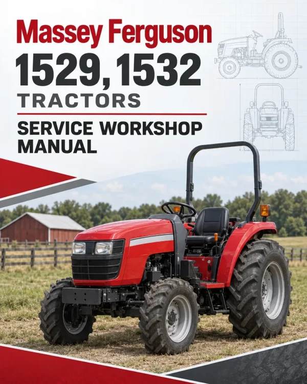
The Massey Ferguson 1529 and 1532 Compact Tractor Workshop Service Manual provides technical information for maintaining, inspecting, troubleshooting and repairing these compact agricultural tractors. It includes major component removal procedures, clutch servicing, transmission repair information, four-wheel-drive axle maintenance, hydraulic system specifications and electrical troubleshooting references.
Coverage includes engine and engine accessory sections, tractor separation, standard and Synchro Shuttle transmissions, power take-off assemblies, rear axle and braking components, front axle servicing and lubrication. Additional chapters address hydraulic pumps, lift control valves, steering-related equipment, electrical sensors, switches, wiring diagrams and system diagnostics.
Notice: The documentation contains separate Standard Transmission and Synchro Shuttle Transmission sections. Select the procedures appropriate to the transmission fitted to the tractor. Engine, Engine Accessories and Lubrication appear as standalone chapters in the supplied bookmark index without additional subsection details.
Table of Contents
Massey Ferguson 1529, 1532 Manual
- 01. General Information
-
02. Major Components
- Platform Removal and Installation
- Splitting the Tractor at the Clutch Housing
- Disassembly of Major Components
- Disassembly of Functional Blocks
- Hood Release and Side Covers
- Radiator
- Removal of Engine
- Separation of Clutch Housing from Spacer Transmission Case
- Separation of Front Transmission Case from Rear Transmission Case
- Separation of Rear Axle Housing from Rear Transmission Case
- Removal of Cylinder Case
- Removal of Front Axle (4WD)
- 03A. Engine
- 03B. Engine Accessories
-
04. Clutch
- Construction
- Disassembly, Inspection and Assembly
- Troubleshooting
- Clutch Housing Plug
-
05. Transmission
- Standard Transmission
- Inspection and Assembly Precautions
- Transmission Flow Diagrams
- Shift Positions
- Disassembly, Inspection and Assembly
- Input Gears and Metal Cover
- Power Take-Off (PTO)
- PTO Gear
- PTO Clutch
- PTO Shift Link
-
06. Synchro Shuttle Transmission
- Shuttle Shift Transmission
- Inspection and Assembly Precautions
- Transmission Flow Diagrams
- Shift Positions
- Main Gears
- Input Gears
- Range Gear System and PTO Gear System
- Range Gear System
- PTO Gear
- PTO Clutch
- PTO Shift Link
- Mid PTO
-
07. Rear Axle and Brakes
- Rear Axle Housing
- Construction
- Disassembly
- Inspection
- Precautions for Assembly
- Brake Adjustment
-
08. Front Axle
- Front Axle
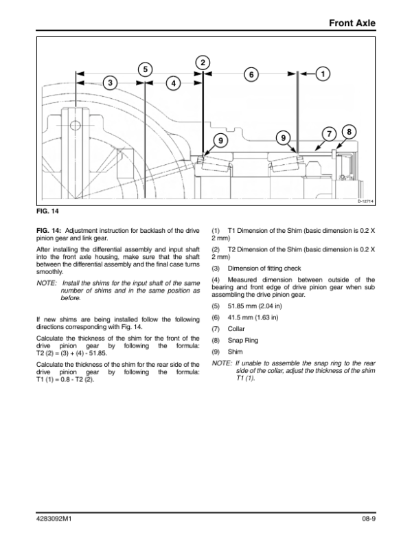
- Four-Wheel-Drive Front Axle
- Disassembly
- Inspection
- Precautions for Assembly
- Front Axle Oil (4WD Only)
- Wheels and Tires
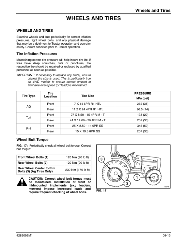
- Tire Inflation Pressures
- Wheel Bolt Torque
- Front Wheel Alignment
- Troubleshooting
- 09. Lubrication
-
10. Hydraulics
- Hydraulic System
- General Description
- Hydraulic System and Circuit Diagrams
- Specifications
- Major Components
- Main Cylinder and Cylinder Case
- Main Control Valve
- Flow Control Valve
- Safety Valve
- Relief Valve
- Gear Pump
- Control Link and Lever
- Operation
- Adjustment
- Components
- Hydraulic System Troubleshooting
-
11. Electrical
- General Electrical
- Safety Switches
- Electrical Formulas
- Battery
- Instrument Panel, Sensors and Relays
- Fuel Gauge Sensor
- Turn / Hazard Lights Switch
- Light Switch
- Glow Plugs
- Engine Glow Plugs
- Instrument Light Bulbs
- Fuse Box and Slow-Blow Fuses
- Relays and Switches
- Electrical Components Layout and Schematics
- Electrical Component Layout
- Electrical Accessories
- Electrical Circuit
- Troubleshooting
Standard and Synchro Shuttle Transmission Service Information
The manual provides separate servicing chapters for the standard transmission and Synchro Shuttle transmission. These sections cover transmission flow diagrams, main and range gear arrangements, input gears, inspection and assembly precautions, and power take-off components. The Synchro Shuttle chapter also includes information on the mid PTO assembly, while the standard transmission chapter covers PTO clutch components and shift linkage.
The hydraulic documentation provides system and circuit diagrams, component specifications, main control valve servicing, gear pump inspection, relief valve operation and control linkage adjustments. Rear axle servicing includes brake adjustment and axle housing procedures, while the front axle chapter addresses four-wheel-drive components, wheel alignment, tire inflation pressures and related troubleshooting.
For electrical diagnosis, the manual includes references for the battery, instrument panel, fuel gauge sensor, glow plugs, safety switches, fuses, relays and electrical circuit layouts. Consult the applicable system chapter and component specifications before starting inspection, adjustment or repair work.

















Reviews
There are no reviews yet.