Overview
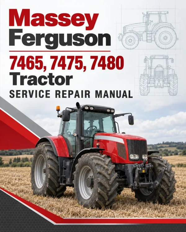
The Massey Ferguson 7465, 7475 and 7480 Tractor Workshop Service Repair Manual provides technical information for servicing, maintaining, diagnosing and repairing these Massey Ferguson 7400 Series agricultural tractors. The documentation covers tractor specifications, major assembly separation, Perkins and Sisu diesel engines, Dyna-VT transmission systems, rear axle and brake assemblies, power take-off components, Carraro front axles, hydraulics, electrical equipment, electronic controls and cab systems.
Workshop coverage includes Dyna-VT gearbox hydraulic testing and unit replacement, engine-to-transmission separation, rear differential and final drive repairs, PTO clutch servicing, four-wheel-drive components, Load Sensing hydraulic systems and electronic fault diagnosis. Detailed references address Perkins EEM and SisuDiesel EEM2 injection systems, Autotronic controls, Datatronic displays, electronic linkage calibration, suspended cab systems and air-conditioning maintenance.
Important Information: The supplied workshop documentation is identified as the MF 7400 Series manual for models up to 2008. It contains procedures for different Perkins and Sisu engine installations, electronic control systems and optional equipment. Verify the tractor model, production specification and installed components before selecting the applicable repair instructions.
Table of Contents
Massey Ferguson 7465, 7475, 7480 Tractor Workshop Manual
-
01. Introduction and Specifications
- 01A01 – Introduction
- Using the Workshop Manual
- Tractor Specifications
- Ground Speeds
- General Dimensions
- Capacities
- Conversion Tables
- Locking Compounds and Sealants
- Tightening Torques
-
02. Splitting the Tractor and Separation of Assemblies
- 02A01 – Splitting the Front Frame / Perkins Engine
- Perkins Six-Cylinder Engine – Disassembly and Reassembly
- 02A02 – Splitting the Front Frame / Sisu Engine
- Sisu Engine – Front Frame Disassembly
- Sisu Engine – Front Frame Reassembly
- 02B01 – Splitting the Perkins Engine / Dyna-VT Gearbox
- Perkins Six-Cylinder Engine – Engine and Transmission Separation
- 02B02 – Splitting the Sisu Engine / Dyna-VT Gearbox
- Sisu Engine – Engine and Transmission Disassembly
- Sisu Engine – Engine and Transmission Reassembly
-
03. Engine
- 03A01 – Engine General Information
- Engine Specifications and Main Characteristics
- Fuel, Engine Oil and Coolant Standards
- 03C01 – EEM2 SisuDiesel – Disassembly and Reassembly
- Replacing the Engine Electronic Control Unit (ECU)
- Disassembling the Fuel Injection Pump
- Reassembling the Fuel Injection Pump
- 03D01 – Engine and Gearbox Spacer
- Removing and Refitting the Spacer
- Replacing the Drive Shaft
- 04. Clutch
-
05. Gearbox – Dyna-VT Transmission
- 05A01 – Dyna-VT Transmission – General Operation
- Dyna-VT Transmission Operating Diagrams
- Transmission Operation and Use
- 05B01 – Dyna-VT Hydraulic System
- Forward and Reverse High-Pressure Relief Valves
- Scavenging Valve
- Control Spool Valve
- Dyna-VT Hydraulic Tests
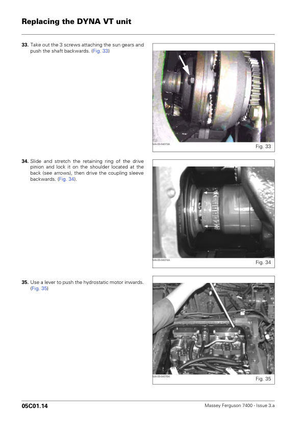
- 05C01 – Replacing the Dyna-VT Unit
- Disassembling the Dyna-VT Unit
- Reassembling the Dyna-VT Unit
- Filling the Gearbox
-
06. Rear Axle and Braking System
- 06B01 – Final Drive Units
- Final Drive – General Information
- Removing a Final Drive Unit
- Refitting a Final Drive Unit
- 06C01 – Braking System
- Rear Axle Brakes – Removal and Refitting
- Rear Axle Brake Reassembly
- Removing a Wheel Brake Cylinder
- Refitting the Wheel Brake Cylinder
- Bleeding the Brakes
- 06D01 – Differential and Drive Pinion
- Differential – General Information
- Removing the Differential
- Refitting the Differential
- Disassembling the Drive Pinion
- Refitting the Drive Pinion
- Differential Disassembly and Reassembly Procedures
-
07. Power Take-Off (PTO)
- 07A01 – Power Take-Off General Information
- 07B01 – Rear Power Take-Off – Disassembly and Reassembly
- Disassembling the PTO Clutch
- Reassembling the Power Take-Off Clutch
- Disassembling the PTO Speed Selector
-
08. Front Axle and Four-Wheel Drive
- 08A01 – Front Axle General Information
- Front Axle Description and Safety Instructions
- 08B01 – Carraro Final Drive Units
- Steering Ram Disassembly
- Epicyclic Drive Unit Removal
- Wheel Hub Disassembly
- Axle Beam Disassembly and Reassembly
- Wheel Hub Reassembly
- Epicyclic Drive Unit Reassembly
- Wheel Alignment Adjustment
- Steering Lock Angle Adjustment
- 08C01 – Carraro Differential
- Splitting the Front Axle and Frame
- Removing the Wheel Hubs, Axle Beam and Steering Ram
- Differential Housing Disassembly
- Differential Gear Disassembly and Reassembly
- Differential Unit Disassembly and Reassembly
- Differential Housing Reassembly
- 08D01 – Bearings and Transmission Shafts – Carraro Front Axle
- Four-Wheel-Drive Transmission Shafts and Universal Joint Spiders
- Bearing Support and Front Axle Removal and Refitting
- Replacing Friction Rings and Seals
- 08E01 – Dyna-VT Four-Wheel-Drive Clutch
- 4WD Clutch Operation
- Disassembling the Four-Wheel-Drive Clutch
- Reassembling the Four-Wheel-Drive Clutch
- 08E02 – Universal Joint Shaft Brake
- Removing the Universal Joint Shaft Brake
- Refitting the Universal Joint Shaft
- 08F01 – Carraro Front Axle Suspension
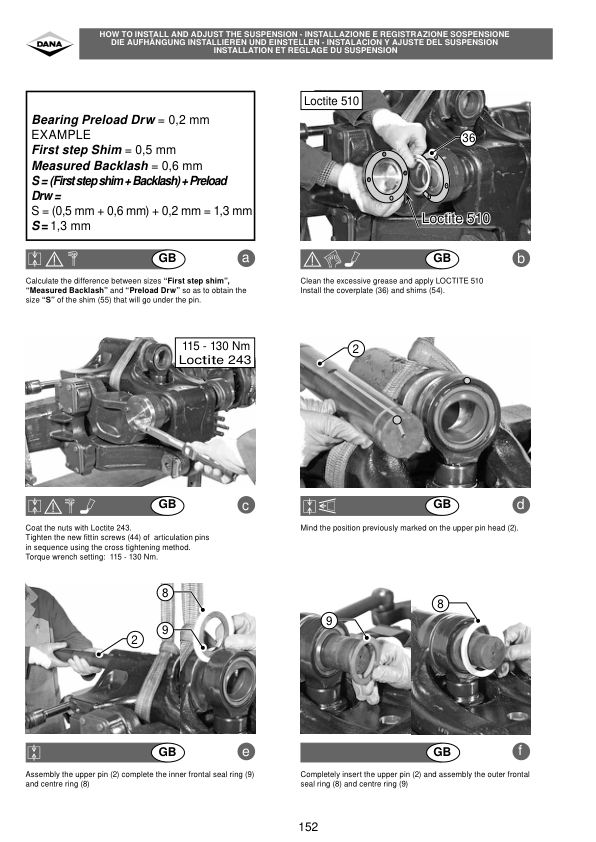
- Suspension Arm Assembly Disassembly
- Suspension Arm Assembly Reassembly
- Suspension Service Tools
- 08G01 – Carraro Front Axle Troubleshooting
- Problem Identification and Diagnostics
-
09. Hydraulics
- 09A01 – Hydraulic Circuit Description
- Hydraulic Component Characteristics
- 09B01 – Illustrated Hydraulic Diagram
- Transmission Hydraulic System Diagram
- 09C01 – Hydraulic Legends and Diagrams
- Transmission Hydraulic Diagram Legend
- Auxiliary Hydraulic Diagram Legend
- Transmission Hydraulics
- Auxiliary Hydraulics
- 09F01 – Auxiliary Load Sensing Spool Valves
- Load Sensing Spool Valve Operation
- Spool Valve Component Layout and Port Identification
- Spool Valve Assembly
- Fitting and Adjusting the Control Cables
- 09F02 – Electrohydraulic Spool Valves
- Electrohydraulic Valve Component Layout
- Electrohydraulic Valve Diagram
- Electrohydraulic Spool Valve Assembly
- Control Lever Location and Cable Adjustment
- 09G01 – Load Sensing Lift Control Valve
- Lift Control Valve Component Layout
- Removing and Refitting the Distribution Block
- Lift Control Valve – Neutral Position
- Lift Control Valve – Lifting Position
- Lift Control Valve – Lowering Position
- Lift Control Valve Assembly
- 09H01 – Load Sensing Hydrostatic Steering
- Hydrostatic Steering Operation
- Load Sensing Operating Principle
- 09I01 – Auxiliary Hydraulic Tests
- Hydraulic Pressure Testing
- Pressure Measuring Points on the Distribution Block
-
10. Electrical Equipment
- 10A01 – Fuse Box
- Perkins Dyna-VT Europe Fuse Box
- Perkins Dyna-VT North American Fuse Box
- Perkins / Sisu Dyna-VT Europe Fuse Box
- Perkins / Sisu Dyna-VT North American Fuse Box
- Germany-Specific Fuse Box References
- Fuse Box Accessories
- 10A02 – Electrical Diagrams
- Cab Equipment Electrical Diagrams
- Engine Equipment Electrical Diagrams
- Bulb Types
- Lighting System Diagrams
- Electronic Control Unit Power Supply
-
11. Electronics and Diagnostic Systems
- 11A10 – Perkins EEM – Description
- Perkins Engine Electronic Management Components
- Tractor and Engine Communication
- GUF111 – Perkins Electronic Injection – Programming
- GUF112 – Perkins Electronic Injection – Tests and Diagnostics
- GUF113 – Perkins Electronic Injection – Error Codes
- GUF115 – Perkins Electronic Injection – Electrical Diagrams
- 11B10 – SisuDiesel EEM2 – Description
- SisuDiesel Engine Electronic Management Components
- GUF101 – SisuDiesel Electronic Injection – Programming
- GUF102 – SisuDiesel Electronic Injection – Tests and Diagnostics
- GUF103 – SisuDiesel Electronic Injection – Error Codes
- SisuDiesel EEM2 Sensor and Controller Diagnostics
- Fuel Injection Pump Diagnostics
- 11B14 – SisuDiesel EEM2 – Calibration
- Throttle Pedal Potentiometer Calibration
- GUF105 – SisuDiesel Electronic Injection – Electrical Diagrams
- 11C10 – DCC2 Dyna-VT – Description
- DOT Matrix Display Operation
- GUF211 – DCC2 Dyna-VT – Programming and Parameter Settings
- GUF213 – DCC2 Dyna-VT – Error Codes
- GUF214 – DCC2 Dyna-VT – Calibrations, Constants and Adjustments
- Ground Speed Calibration
- Throttle Pedal Potentiometer Calibration
- CAL 2 and CAL 3 Settings
- Diagnostic Mode
- Manoeuvring Pedal Adjustment
- GUF215 – DCC2 Dyna-VT – Electrical Diagrams
- 11D10 – Autotronic 4 – Description
- Autotronic 4 Instrument Panel and Controls
- Armrest and Forward/Neutral/Reverse Lever Operation
- GUF401 – Autotronic 4 – Programming and Parameter Settings
- GUF402 – Autotronic 4 – Tests and Diagnostics
- Gearbox, Front Axle, Differential and PTO Diagnostic Functions
- GUF403 – Autotronic 4 – Error Codes
- GUF404 – Autotronic 4 – Calibration
- Hare/Tortoise Range and Transmission Calibration
- Coupler and Power Take-Off Calibration
- GUF405 – Autotronic 4 – Electrical Diagrams
- 11E10 – Electronic Linkage – Description
- GUF51 – EHRC Linkage – Parameter Settings
- GUF52 – EHRC Linkage – Tests and Diagnostics
- GUF53 – EHRC Linkage – Error Codes
- GUF54 – EHRC Linkage – Adjustments
- GUF55 – EHRC Linkage – Electrical Diagrams
- GUF521 – Autotronic 5 Linkage – Programming and Parameter Settings
- GUF522 – Autotronic 5 Linkage – Tests and Diagnostics
- GUF523 – Autotronic 5 Linkage – Error Codes
- GUF524 – Autotronic 5 Linkage – Calibration and Adjustments
- GUF525 – Autotronic 5 Linkage – Electrical Diagrams
- 11F10 – Datatronic 2 – Description
- GUF61 – Datatronic 2 – Programming and Parameter Settings
- GUF62 – Datatronic 2 – Tests and Diagnostics
- GUF63 – Datatronic 2 – Error Codes
- GUF64 – Datatronic 2 – Calibration
- GUF65 – Datatronic 2 – Electrical Diagrams
- 11F16 – Datatronic 2 – Front Dual Control
- 11F17 – Datatronic 2 – Dual Control for Semi-Mounted Implements
- 11F18 – Datatronic 2 – Trailed Implement Control (TIC)
- GUF600 – Datatronic 3 – General
- GUF601 – Datatronic 3 – Programming
- GUF604 – Datatronic 3 – Calibration and Adjustments
- GUF605 – Datatronic 3 – Electrical Diagrams
- 11G10 – SMS Joystick – Description
- GUF71 – SMS Joystick – Parameter Settings
- GUF72 – SMS Joystick – Tests and Diagnostics
- GUF73 – SMS Joystick – Error Codes
- GUF74 – SMS Joystick – Calibration and Settings
- GUF75 – SMS Joystick – Electrical Diagrams for EHRC Linkage
- GUF75 – SMS Joystick – Electrical Diagrams for Autotronic 5 Linkage
- 11H10 – Suspended Front Axle – Electronic Control Description
- Suspension Control System
- Suspension Sensor Removal and Reassembly
- Suspension Electronic Control Unit
-
12. Cab and Equipment
- 12B01 – Suspended Cab
- Suspended Cab Operating Principles
- Suspension Control Unit
- Suspension Electrical Circuit Operation
- Suspension Pneumatic Operation
- Cab Angular Travel
- Suspension Controls and Diagnostics
- 12C01 – Air Conditioning – General Information
- Air Conditioning Technical Characteristics
- Air Conditioning Safety Instructions
- General Maintenance and Circuit Troubleshooting
- 12C02 – Standard Air Conditioning
- Standard Air Conditioning Electrical Diagram
- 12C03 – Automatic Air Conditioning
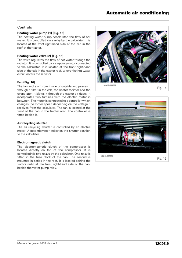
- Automatic Air Conditioning Operating Principles
- Automatic Air Conditioning Component Layout
- Automatic Air Conditioning Troubleshooting
- Automatic Air Conditioning Electrical Diagram
- GUF302 – Automatic Air Conditioning – Tests and Diagnostics
- GUF303 – Automatic Air Conditioning – Error Codes
- GUF305 – Automatic Air Conditioning – Electrical Diagrams
- 12C04 – Refilling the Air Conditioning Unit
- Draining the Refrigerant Circuit and Checking for Leaks
- Air Conditioning System Evacuation and Leak Detection
- Refilling the Unit with the Engine Stopped
- Checking Refrigerant Pressures
- Air Conditioning Service Tools
- 13. Accessories
- 14. Service Tools
Dyna-VT Transmission and Electronic Diagnostic Information
The Massey Ferguson 7465, 7475 and 7480 workshop documentation includes detailed procedures for Dyna-VT gearbox servicing, rear axle and PTO repairs, Carraro front axle maintenance, hydraulic pressure testing and electrical troubleshooting. Electronic service sections cover Perkins and Sisu engine management, Autotronic and Datatronic systems, linkage calibration and diagnostic fault codes, while the cab chapters provide suspension and air-conditioning service references.


















Reviews
There are no reviews yet.