506 HTR Transmission, Synchro Shuttle and Power Shuttle Servicing
The 506 HTR transmission documentation provides technical information for multiple drivetrain configurations, including 8+8 Synchro Shuttle, 12+12 Synchro Shuttle, 24+24 Synchro Shuttle with Synchro Splitter, 24+24 Synchro Shuttle with Power Splitter, 12+12 Power Shuttle and 24+24 Power Shuttle with Synchro Splitter arrangements. It includes transmission identification, mechanical operating principles, power flow diagrams, lubrication references, assembly measurements and component servicing procedures.
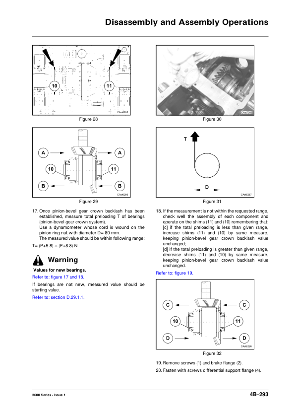
Detailed repair sections address wet clutch assemblies, Power Shuttle and Power Splitter components, transmission input shafts, primary and secondary shafts, range gears, synchronisers, clutch housings, final drives and PTO mechanisms. Additional references include clutch pack wear inspection, bearing preload adjustments, hydraulic valve servicing, differential locking mechanisms and parking brake components.
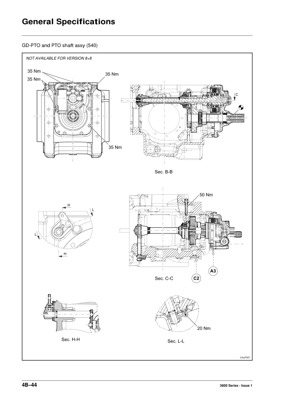
The transmission also contains separate servicing information for PTO wet clutches, PTO input and output shafts, PTO braking and ground drive PTO equipment. Technicians should identify the transmission version and PTO arrangement before selecting the appropriate disassembly, reassembly or adjustment procedure.
Differential, Front Axle and Steering Repair Information
The differential chapter provides assembly and disassembly procedures, while the transmission documentation contains additional differential servicing references. The two-wheel-drive front axle chapter covers steering cylinders, wheel hubs, hub supports, axle beams and steering geometry adjustments.
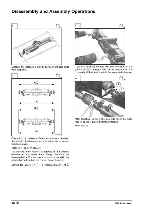
Technical information includes axle identification, maintenance, lubrication, tightening torques, toe-in adjustments, steering angle settings and troubleshooting. A separate Front Axle chapter is also identified in the workshop documentation. Select the applicable axle information according to the tractor’s configuration.
Hydraulic System Operation and Control Valve Adjustments
The general workshop information includes hydraulic system components, rockshaft valve servicing, hydraulic pump removal and installation, auxiliary distributors, Power Shuttle hydraulic valves and hydraulic oil filtering components.
The hydraulic lifting system references describe control valve operation, internal linkage mechanisms, position control, draft control and combined position/draft operation. Additional procedures address control valve sensitivity, position lever and draft lever adjustments, reaction spring inspection, push rod measurements and hydraulic troubleshooting.
Power Shuttle Electrical Diagrams and Serial Number Amendments
The amendment includes additional electrical wiring diagrams and Power Shuttle testing procedures. It identifies Power Shuttle EHM 24 systems used before serial number CS20011, a Trax 56-pin conversion kit for earlier tractors, and Trax 56-pin production wiring effective from serial number CS20011.
Other electrical references distinguish COM2/Tier 2 and COM3/Tier 3 engine configurations, including North American platform wiring. The Power Shuttle amendment contains hydraulic flow information, testing specifications and clutch pressure-testing procedures. Separate fault-code references are provided for tractors manufactured before serial number CS20011 and those equipped with TRAX 56-pin EHM equipment.
Use the tractor’s serial number and installed electronic control components when selecting the appropriate wiring diagram or fault-code information. This distinction is particularly important when diagnosing Power Shuttle operation or servicing tractors with updated electrical equipment.























Reviews
There are no reviews yet.