Overview
The Massey Ferguson 5608, 5609 and 5610 Dyna-4 Classic Tractor Workshop Service Repair Manual provides detailed technical information for servicing, maintaining, diagnosing and repairing these Massey Ferguson 5600 Series agricultural tractors. The documentation includes tractor specifications, major assembly removal, engine servicing references, gearbox and transmission repairs, rear axle components, power take-off systems, front axle assemblies, hydraulics, electrical equipment and specialist workshop tools.
Technical coverage includes Dyna-4 PowerShuttle and Powershift transmission components, GBA50 and GBA25 gearboxes, GPA50 rear axle assemblies, differential and braking systems, electrohydraulic PTO mechanisms, Dana front axles, hydraulic steering and Open Centre hydraulic systems. Additional sections cover electrical wiring diagrams, electronic fault codes, hydraulic pressure testing, gearbox calibrations, brake adjustments, component disassembly and reassembly, and troubleshooting procedures.
Important Information: The source publication covers the wider MF 5600 Series, including MF 5611, 5612 and 5613 tractors and additional Dyna-6 or optional equipment configurations. Select the specifications and service procedures applicable to your MF 5608, 5609 or 5610 tractor.
Table of Contents
Massey Ferguson 5608, 5609, 5610 Manual
-
01. Introduction and Specifications
- 1A10 – MF 5600 General Information
- 1A11 – MF 5600 Error Codes
- 1A12 – Fuse Boxes, Electrical Diagrams, Wiring Harnesses and Hydraulic Diagrams
- 1A16 – Adjustments, Bleeding and Calibrations
-
02. Separation of Assemblies
- 2A17 – Front Linkage – Removal and Refitting
- 2B17 – Front Axle – Removal and Refitting
- 2C17 – Cooling Unit – Removal and Refitting
- 2D17 – Front Frame – Removal and Refitting
- 2E17 – Bonnet – Removal and Refitting
- 2F17 – Engine – Removal and Refitting
- 2G17 – Gearbox – Removal and Refitting
- 2H17 – Cab – Removal and Refitting
- 2J17 – Rear Axle – Removal and Refitting
- 2K17 – Rear PTO – Disassembly and Reassembly
- 03. Engine
- 04. Clutch
-
05. Gearbox
- 5A10 – GBA50 – General Information
- 5A13 – GBA50 – Layout of Components
- 5A16 – GBA50 – Adjustments, Bleeding and Calibrations
- 5A17 – GBA50 – Disassembly and Reassembly
- 5A20 – GBA50 PowerShuttle – General Information
- 5A23 – GBA50 PowerShuttle – Layout of Components
- 5A27 – GBA50 PowerShuttle – Disassembly and Reassembly
- 5A28 – GBA50 PowerShuttle – Service Tools
- 5A30 – GBA50 Powershift Module – General Information
- 5A33 – GBA50 Powershift Module – Layout of Components
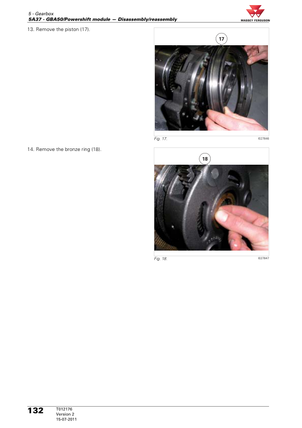
- 5A37 – GBA50 Powershift Module – Disassembly and Reassembly
- 5A38 – GBA50 Powershift Module – Service Tools
- 5A40 – GBA50 Robotic Mechanical Gearbox – General Information
- 5A43 – GBA50 Robotic Mechanical Gearbox – Layout of Components
- 5A47 – GBA50 Robotic Mechanical Gearbox – Disassembly and Reassembly
- 5A48 – GBA50 Robotic Mechanical Gearbox – Service Tools
- 5A60 – GBA50 Super Creeper Gears – General Information
- 5A63 – GBA50 Super Creeper Gears – Layout of Components
- 5A66 – GBA50 Super Creeper Gears – Adjustments and Calibrations
- 5A67 – GBA50 Super Creeper Gears – Disassembly and Reassembly
- 5A68 – GBA50 Super Creeper Gears – Service Tools
- 5B10 – GBA25 – General Information
- 5B13 – GBA25 – Layout of Components
- 5B16 – GBA25 – Adjustments, Bleeding and Calibrations
- 5B17 – GBA25 – Disassembly and Reassembly
- 5B20 – GBA25 PowerShuttle – General Information
- 5B23 – GBA25 PowerShuttle – Layout of Components
- 5B27 – GBA25 PowerShuttle – Disassembly and Reassembly
- 5B28 – GBA25 PowerShuttle – Service Tools
- 5B30 – GBA25 Powershift Module – General Information
- 5B33 – GBA25 Powershift Module – Layout of Components
- 5B37 – GBA25 Powershift Module – Disassembly and Reassembly
- 5B38 – GBA25 Powershift Module – Service Tools
- 5B40 – GBA25 Robotic Mechanical Gearbox – General Information
- 5B43 – GBA25 Robotic Mechanical Gearbox – Layout of Components
- 5B47 – GBA25 Robotic Mechanical Gearbox – Disassembly and Reassembly
- 5B48 – GBA25 Robotic Mechanical Gearbox – Service Tools
- 5B50 – GBA25 Creeper Gears – General Information
- 5B53 – GBA25 Creeper Gears – Layout of Components
- 5B57 – GBA25 Creeper Gears – Disassembly and Reassembly
- 5B60 – GBA25 Super Creeper Gears – General Information
- 5B63 – GBA25 Super Creeper Gears – Layout of Components
- 5B67 – GBA25 Super Creeper Gears – Disassembly and Reassembly
-
06. Rear Axle
- 6A10 – GPA50 – General Information
- 6A13 – GPA50 – Layout of Components
- 6A17 – GPA50 – Disassembly and Reassembly
- 6A20 – GPA50 Trumpet Housings – General Information
- 6A23 – GPA50 Trumpet Housings – Layout of Components
- 6A26 – GPA50 Trumpet Housings – Adjustments and Calibrations
- 6A27 – GPA50 Trumpet Housings – Disassembly and Reassembly
- 6A28 – GPA50 Trumpet Housings – Service Tools
- 6A30 – GPA50 Rear Crown Wheel and Pinion 9×40 and 10×42 – General Information
- 6A33 – GPA50 Rear Crown Wheel and Pinion – Layout of Components
- 6A36 – GPA50 Rear Crown Wheel and Pinion – Adjustments and Calibrations
- 6A37 – GPA50 Rear Crown Wheel and Pinion – Disassembly and Reassembly
- 6A38 – GPA50 Rear Crown Wheel and Pinion – Service Tools
- 6A40 – GPA50 Tractor Braking – General Information
- 6A43 – GPA50 Tractor Braking – Layout of Components
- 6A46 – GPA50 Tractor Braking – Adjustments, Bleeding and Calibrations
- 6A47 – GPA50 Tractor Braking – Disassembly and Reassembly
- 6A48 – GPA50 Tractor Braking – Service Tools
- 6A80 – GPA50 Linkage and Hitch – General Information
- 6A83 – GPA50 Linkage and Hitch – Layout of Components
- 6A87 – GPA50 Linkage and Hitch – Disassembly and Reassembly
- 6A88 – GPA50 Linkage and Hitch – Service Tools
- 6A90 – GPA50 Wheels and Hubs – General Information
- 6A93 – GPA50 Wheels and Hubs – Layout of Components
- 6A96 – GPA50 Wheels and Hubs – Adjustments and Calibrations
- 6A97 – GPA50 Wheels and Hubs – Disassembly and Reassembly
-
07. Power Take-Off (PTO)
- 7A10 – GPA50 Rear PTO with Two Electrohydraulic Speeds – General
- 7A13 – Two-Speed Rear PTO – Layout of Components
- 7A16 – Two-Speed Rear PTO – Adjustments and Calibrations
- 7A17 – Two-Speed Rear PTO – Disassembly and Reassembly
- 7A18 – Two-Speed Rear PTO – Service Tools
- 7A20 – GPA50 Rear PTO with Three Electrohydraulic Speeds – General
- 7A23 – Three-Speed Rear PTO – Layout of Components
- 7A26 – Three-Speed Rear PTO – Adjustments and Calibrations
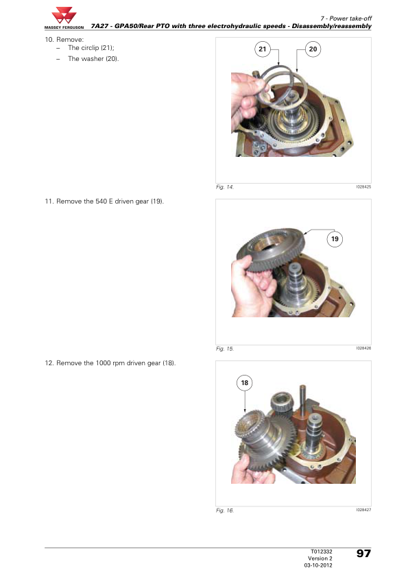
- 7A27 – Three-Speed Rear PTO – Disassembly and Reassembly
- 7A28 – Three-Speed Rear PTO – Service Tools
- 7A30 – GPA50 Ground Speed PTO (GSPTO) – General
- 7A33 – GPA50 GSPTO – Layout of Components
- 7A36 – GPA50 GSPTO – Adjustments and Calibrations
- 7A37 – GPA50 GSPTO – Removal and Refitting
- 7A38 – GPA50 GSPTO – Service Tools
- 7A40 – GPA50 Rear PTO Clutch – General Information
- 7A43 – GPA50 Rear PTO Clutch – Layout of Components
- 7A47 – GPA50 Rear PTO Clutch – Disassembly and Reassembly
- 7A48 – GPA50 Rear PTO Clutch – Service Tools
- 7C10 – Zuidberg Front PTO – General Information
- 7C12 – Zuidberg Front PTO – Electrical and Hydraulic Diagrams
- 7C13 – Zuidberg Front PTO – Layout of Components
- 7C14 – Zuidberg Front PTO – Tests and Diagnostics
- 7C16 – Zuidberg Front PTO – Adjustments and Calibrations
- 7C17 – Zuidberg Front PTO – Disassembly and Reassembly
-
08. Front Axle
- 8A10 – DANA 725 Front Axle – General Information
- 8A13 – DANA 725 Front Axle – Layout of Components
- 8A14 – DANA 725 Front Axle – Tests and Diagnostics
- 8A17 – DANA 725 Front Axle – Disassembly and Reassembly
- 8A20 – DANA 730 Front Axle – General Information
- 8A23 – DANA 730 Front Axle – Layout of Components
- 8A24 – DANA 730 Front Axle – Tests and Diagnostics
- 8A27 – DANA 730 Front Axle – Removal and Refitting
- 8B10 – Suspended Front Axle – General Information
- 8B13 – Suspended Front Axle – Layout of Components
- 8B17 – Suspended Front Axle – Removal and Refitting
- 8G10 – GPA50 Four-Wheel Drive Clutch – General Information
- 8G13 – GPA50 Four-Wheel Drive Clutch – Layout of Components
- 8G16 – GPA50 Four-Wheel Drive Clutch – Adjustments and Calibrations
- 8G17 – GPA50 Four-Wheel Drive Clutch – Disassembly and Reassembly
- 8G18 – GPA50 Four-Wheel Drive Clutch – Service Tools
- 8I10 – Open Centre Steering Unit – General Information
- 8I13 – Open Centre Steering Unit – Layout of Components
- 8I17 – Open Centre Steering Unit – Disassembly and Reassembly
- 8J10 – Closed Centre Steering Unit – General Information
- 8J13 – Closed Centre Steering Unit – Layout of Components
- 8J17 – Closed Centre Steering Unit – Removal and Refitting
- DANA 730 – Maintenance and Lubrication
- DANA 730 – Safety Precautions
- DANA 730 – Planetary Reduction Gear
- DANA 730 – Steering Knuckle
- DANA 730 – Steering Sensor
- DANA 730 – Steering Cylinder
- DANA 730 – Differential
- DANA 730 – Bevel Pinion
- DANA 730 – Special Tools
-
09. Hydraulics
- 9A10 – GPA50 Open Centre – General Information
- 9A13 – GPA50 Open Centre – Layout of Components
- 9A14 – GPA50 Open Centre – Tests and Diagnostics
- 9A18 – GPA50 Open Centre – Service Tools
- 9A20 – GPA50 Open Centre Right-Hand Cover Plate – General
- 9A23 – GPA50 Open Centre Right-Hand Cover Plate – Layout of Components
- 9A27 – GPA50 Open Centre Right-Hand Cover Plate – Removal and Refitting
- 9B10 – GPA50 100 L/min Open Centre – General Information
- 9B13 – GPA50 100 L/min Open Centre – Layout of Components
- 9B14 – GPA50 100 L/min Open Centre – Tests and Diagnostics
- 9B18 – GPA50 Open Centre – Service Tools
- 9B20 – GPA50 100 L/min Open Centre Right-Hand Cover Plate – General
- 9B23 – GPA50 100 L/min Open Centre Right-Hand Cover Plate – Layout of Components
- 9B27 – GPA50 100 L/min Open Centre Right-Hand Cover Plate – Removal and Refitting
- 9B30 – GPA50 100 L/min Open Centre Left-Hand Cover Plate – General
- 9B33 – GPA50 100 L/min Open Centre Left-Hand Cover Plate – Layout of Components
- 9B37 – GPA50 100 L/min Open Centre Left-Hand Cover Plate – Removal and Refitting
- 9C10 – GPA50 Closed Centre – General Information
- 9C13 – GPA50 Closed Centre – Layout of Components
- 9C14 – GPA50 Closed Centre – Tests and Diagnostics
- 9C18 – GPA50 Closed Centre – Service Tools
- 9C20 – GPA50 Closed Centre Right-Hand Cover Plate – General
- 9C23 – GPA50 Closed Centre Right-Hand Cover Plate – Layout of Components
- 9C27 – GPA50 Closed Centre Right-Hand Cover Plate – Removal and Refitting
- 9C30 – GPA50 Closed Centre Left-Hand Cover Plate – General
- 9C33 – GPA50 Closed Centre Left-Hand Cover Plate – Layout of Components
- 9C37 – GPA50 Closed Centre Left-Hand Cover Plate – Removal and Refitting
- 9D10 – GPA50 Open Centre Spool Valves – General Information
- 9D13 – GPA50 Open Centre Spool Valves – Layout of Components
- 9D17 – GPA50 Open Centre Spool Valves – Removal and Refitting
- 9D20 – GPA50 Open Centre Rear Linkage – General Information
- 9D23 – GPA50 Open Centre Rear Linkage – Layout of Components
- 9D24 – GPA50 Open Centre Rear Linkage – Tests and Diagnostics
- 9C27 – GPA50 Open Centre Rear Linkage – Removal and Refitting
- 9D30 – GPA50 Open Centre Front Linkage – General Information
- 9D33 – GPA50 Open Centre Front Linkage – Layout of Components
- 9D36 – GPA50 Open Centre Front Linkage – Adjustments and Calibrations
- 9D40 – GPA50 Open Centre Mid-Mounted – General Information
- 9D43 – GPA50 Open Centre Mid-Mounted – Layout of Components
- 9D46 – GPA50 Open Centre Mid-Mounted – Adjustments and Calibrations
- 9D47 – GPA50 Open Centre Mid-Mounted – Removal and Refitting
- 9E10 – GPA50 Closed Centre Spool Valves – General Information
- 9E13 – GPA50 Closed Centre Spool Valves – Layout of Components
- 9E17 – GPA50 Closed Centre Spool Valves – Removal and Refitting
- 9E20 – GPA50 Closed Centre Rear Linkage – General Information
- 9E23 – GPA50 Closed Centre Rear Linkage – Layout of Components
- 9E27 – GPA50 Closed Centre Rear Linkage – Removal and Refitting
- 9E33 – GPA50 Closed Centre Front Linkage – Layout of Components
- 9E36 – GPA50 Closed Centre Front Linkage – Adjustments and Calibrations
- 9E40 – GPA50 Closed Centre Mid-Mounted – General Information
- 9E43 – GPA50 Closed Centre Mid-Mounted – Layout of Components
- 9E46 – GPA50 Closed Centre Mid-Mounted – Adjustments and Calibrations
- 9E47 – GPA50 Closed Centre Mid-Mounted – Removal and Refitting
- 9F10 – GPA50 Brake Master Cylinders – General Information
- 9F13 – GPA50 Brake Master Cylinders – Layout of Components
- 9F16 – GPA50 Brake Master Cylinders – Adjustments and Calibrations
- 9F18 – GPA50 Brake Master Cylinders – Service Tools
- 9F20 – GPA50 Open Centre Hydraulic Trailer Braking – General
- 9F23 – GPA50 Open Centre Hydraulic Trailer Braking – Layout of Components
- 9F26 – GPA50 Open Centre Hydraulic Trailer Braking – Adjustments and Calibrations
- 9F28 – GPA50 Open Centre Hydraulic Trailer Braking – Service Tools
- 9F30 – GPA50 Closed Centre Hydraulic Trailer Braking – General
- 9F36 – GPA50 Closed Centre Hydraulic Trailer Braking – Adjustments and Calibrations
-
10. Electricity
- 10A12 – Lighting and Equipment – Electrical Diagrams
- 10A13 – Lighting and Equipment – Layout of Components
- 10B10 – Fuse Box – General Information
- 10B12 – Fuse Box – Electrical and Hydraulic Diagrams
- 10B13 – Fuse Box – Layout of Components
- 10B17 – Fuse Box – Disassembly and Reassembly
- 10C14 – Alternator – Tests and Diagnostics
- 10C17 – Alternator – Disassembly and Reassembly
- 10C18 – Alternator – Service Tools
- 10E10 – Starter – General Information
- 10E14 – Starter – Tests and Diagnostics
- 10E17 – Starter – Disassembly and Reassembly
- 10F17 – Triflash Triangle – Assembly
- 11. Electronics
- 12. Cab and Equipment
- 13. Accessories
-
14. Service Tools
- 14A01 – General
- 14A02 – Separation of Assemblies
- 14A03 – Engine
- 14A05 – Gearbox
- 14A07 – Power Take-Off
- 14A08 – Front Axle
- 14A09 – Hydraulics
- 14A10 – Electricity
- 14A12 – Cab
Dyna-4 Transmission, PowerShuttle and GPA50 Rear Axle Service
The Massey Ferguson 5608, 5609 and 5610 workshop manual includes technical procedures for PowerShuttle and Dyna-4 gearbox servicing, transmission calibration, GPA50 rear axle and differential repairs, PTO clutch maintenance, Dana front axle components, hydraulic pressure testing and electrical troubleshooting. Its diagrams, component references and adjustment instructions support workshop diagnosis, maintenance and tractor repairs.




























Reviews
There are no reviews yet.