Overview
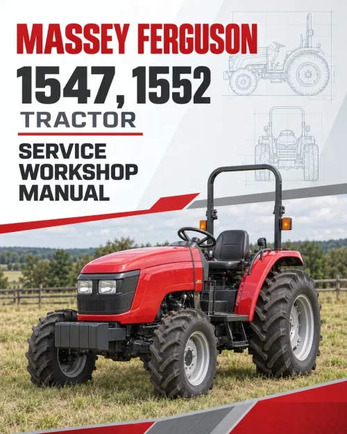
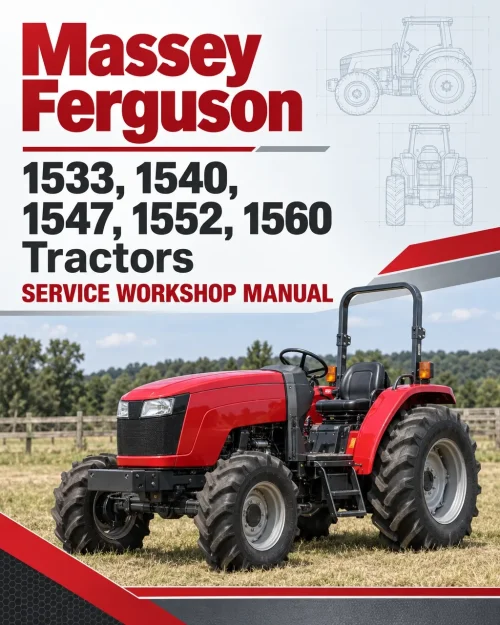
The Massey Ferguson 6265, 6270, 6280 and 6290 Tractor Workshop Service Manual provides detailed technical information for maintaining, diagnosing and repairing these Massey Ferguson 6200 Series tractors. It includes workshop specifications, component identification, dismantling and assembly procedures, mechanical adjustments, hydraulic circuit information and electronic system troubleshooting references.
Coverage includes engine flywheels and dampers, spring-loaded and pressure-loaded clutches, Power Shuttle transmissions, Speedshift and Dynashift systems, rear axle components, power take-off assemblies and Dana and Carraro front axles. Additional chapters address hydraulic steering, braking circuits, electrical equipment, Autotronic controls, Datatronic 2, electronic linkage systems and Wintest diagnostics, with separate references for different equipment configurations.
Safety: The introductory section includes safety precautions and workshop installation guidance, while the Carraro front axle documentation contains dedicated safety instructions. Review the applicable procedures before separating tractor assemblies, servicing pressurized systems or performing component repairs.
Table of Contents
Massey Ferguson 6265, 6270, 6280, 6290 Manual
- 1. Introduction
- 2. Splitting the Tractor
- 2 A01 Engine / Gearbox Splitting
- 2 B01 Between the Gearbox and the Rear Axle
- 2 C01 Between the Front Frame and the Engine
- 3. Engine
- 3 A01 General
- 3 B01 Flywheel and Dampers
- 3 C01 Spacers – Spring-Loaded Clutch
- 3 C02 Spacers – Pressure-Loaded Clutch
- 3 C03 Spacers – Power Shuttle
- 4. Clutch
- 4 A01 Spring-Loaded Clutch
- 4 B01 Pressure-Loaded Clutch
- 5. Gearbox
- 5 A01 General – Operation
- 5 B01 Input Unit with Power Shuttle
- 5 B02 Input Unit
- 5 B03 Speedshift with Power Shuttle
- 5 B04 Speedshift with Mechanical Reverse Shuttle
- 5 B05 Dynashift Unit with Power Shuttle
- 5 B06 Dynashift Unit with Mechanical Reverse Shuttle
- 5 B07 Power Shuttle
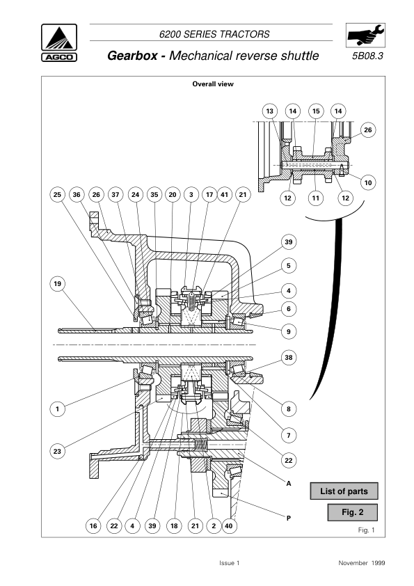
- 5 B08 Mechanical Reverse Shuttle
- 5 C01 Selector Cover with Power Shuttle
- 5 C02 Selector Cover with Power Shuttle
- 5 C03 Selector Cover – Optimised Hare/Tortoise Function
- 5 C04 Selector Cover – Optimised Hare/Tortoise Function
- 5 D01 Selector Rails and Forks
- 5 D02 Selector Rails and Forks – Optimised Hare/Tortoise Function
- 5 E01 Output Shaft – Normal Duty Gearbox
- 5 E02 Output Shaft – Heavy Duty Gearbox
- 5 F01 Layshaft – Normal Duty Gearbox
- 5 F02 Layshaft – Heavy Duty Gearbox
- 5 G01 Mainshaft – Normal Duty Gearbox
- 5 G02 Mainshaft – Heavy Duty Gearbox
- 5 H01 Creeper Gears
- 6. Rear Axle
- 6 A01 Rear Axle Description
- 6 B01 Lift Cover
- 6 C01 Trumpet Housings
- 6 C02 Reinforced Trumpets
- 6 D01 Handbrake
- 6 E01 Differential
- 6 F01 Brake Pistons and Seals
- 6 G01 Brackets and Automatic Hook
- 6 H01 Rear Hitch
- 7. Power Take-Off
- 7 A01 Layshaft – Driving Pinion – PTO Brake
- 7 B01 Removable PTO Shaft
- 7 C01 Shiftable Power Take-Off Shaft
- 7 D01 Power Take-Off Proportional to Forward Speed
- 7 E01 PTO Clutch
- 8. Front Axle
- 8 A01 General Description of Carraro Front Axle
- 8 B01 Dana Final Drive Units
- 8 B02 Carraro Final Drive Units
- 8 C01 Dana Differential
- 8 C02 Carraro Differential
- 8 D01 2 RM Front Axle Beam
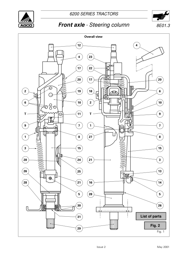
- 8 E01 Steering Column
- 8 F01 Bearings and Transmission Shaft – Dana Front Axle
- 8 F02 Bearings and Transmission Shafts
- 8 G01 4WD Clutch Assembly
- 8 G02 Carraro Suspension
- 8 I01 Carraro Troubleshooting
- 9. Hydraulics
- 9 A01 Description of the Circuit
- 9 B01 Trailer Braking
- 9 C01 Auxiliary Spool Valves
- 9 D01 Lift Control Valve
- 9 E01 Hydrostatic Steering
- 9 F01 Low-Pressure Components
- 9 G01 Brake and Clutch Master Cylinder Circuits and Bleeding
- 9 H01 17 Bar Valve
- 9 I01 Right-Hand Hydraulic Cover
- 9 I02 Left-Hand Cover
- 9 J01 Clutch Control Valve
- 9 K01 Power Shuttle Control Block
- 9 K02 Hydraulic Control Unit – Suspended Front Axle
- 9 L01 Dynashift or Speedshift Control
- 9 M01 Tests
- 9 N01 Description of the Circuit
- 9 P01 Priority Block with Trailer Braking
- 9 Q01 Priority Block without Trailer Braking
- 9 R01 Auxiliary Spool Valves
- 9 R02 Electro-Hydraulic Spool Valves
- 9 S01 Lift Control Valve
- 9 T01 Hydrostatic Steering
- 9 U01 Right-Hand Cover
- 9 U02 Left-Hand Cover
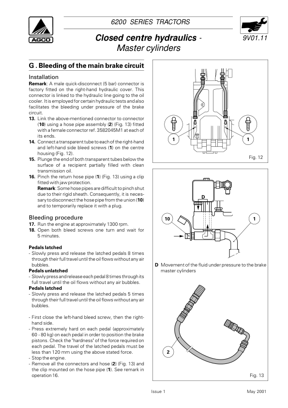
- 9 V01 Clutch and Brake Master Cylinder Circuit and Bleeding
- 9 W01 Tests
- 10. Electrical Equipment
- 10 A01 Rists Electrical Equipment
- 10 A02 Deutsch Electrical Equipment
- 11. Electronics
- 11 A01 Description
- 11 A02 Checks without a Tester
- 11 B01 Description
- 11 C01 Description of Electronic Linkage – Cab Tractor
- 11 C02 Linkage Auto-Diagnostics – Cab Tractor
- 11 D01 Datatronic 2 – Description
- 11 D02 Front Dual Control
- 11 D03 Dual Control for Semi-Mounted Implement
- 11 D04 TIC for Semi-Mounted Implements
- 11 F01 Wintest – General
- 11 F02 Autotronic 2 with Wintest
- 11 F03 Autotronic 3 with Wintest
- 11 F04 TC and DCC with Wintest
- 11 F05 Electronic Linkage with Wintest
- 11 F06 Datatronic 2 with Wintest
- 11 F07 Joystick with Wintest
- 11 G01 Carraro Suspension
- 11 H01 Description
- 12. Cab and Equipment
- 13. Accessories
- 14. Service Tools
Transmission Variants and Electronic Diagnostic Systems
The gearbox chapters distinguish Normal Duty and Heavy Duty transmission components, Power Shuttle and mechanical reverse shuttle arrangements, and Speedshift and Dynashift units. Separate sections cover selector mechanisms, Hare/Tortoise range controls, creeper gears, output shafts, layshafts and mainshafts. Identify the installed transmission, clutch type and shifting system before following the corresponding disassembly, adjustment or repair procedures.
The electrical and electronic documentation includes Rists and Deutsch equipment arrangements, Autotronic 2 and Autotronic 3 systems, Datatronic 2, electronic linkage controls and Wintest diagnostic procedures. The Wintest sections address system testing, programming, calibration and error-code references. Consult the material appropriate to the tractor’s electrical equipment and electronic control configuration.
The front axle and hydraulic chapters provide additional configuration-specific information for Dana and Carraro axles, suspended front axle controls, hydrostatic steering, trailer braking, hydraulic priority blocks and auxiliary spool valves. Use the relevant system diagrams, pressure-test procedures and component specifications when diagnosing or servicing the installed equipment.




















Reviews
There are no reviews yet.