Overview
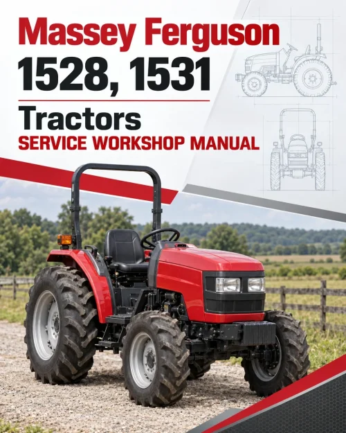
The Massey Ferguson 1433V and 1440V Compact Tractor Service Repair Manual provides technical information for workshop maintenance, troubleshooting and repair of these compact tractors. The documentation covers component identification, inspection procedures, disassembly and installation, mechanical adjustments and servicing references for the tractor’s major operating systems.
Coverage includes chassis and sheet-metal components, three-point hitch equipment, engine-related systems, clutch and transmission servicing, front and rear axles, braking, hydraulics and electrical equipment. The transmission chapter includes mechanical shuttle mechanisms, gear assemblies, differential components and power take-off servicing, while the hydraulic and electrical sections provide additional component testing and troubleshooting information.
Notice: The sheet-metal section includes references to ST35, ST40, MT265 and MT285 models alongside the Massey Ferguson 1433 and 1440. Verify the applicable components before using those procedures. The source bookmarks identify Chapter 08A simply as “Hydrostatic,” without specifying its detailed subsections.
Table of Contents
Massey Ferguson 1433V, 1440V Manual
- 01. Introduction
- 01A. Sheet Metal and Three-Point Hitch
- Sheet Metal and Three-Point Linkage
- Hood Side Panels (ST35 / ST40 / MT265 / MT285)
- Front Grille (ST35 / ST40 / MT265 / MT285)
- Hood (ST35 / ST40 / MT265 / MT285)
- Hood (1433 / 1440)
- Steering Column Covers
- Instrument Cover and Cowling
- ROPS Frame
- Fender
- Seat
- Seat Suspension and Seat Panel
- Platform
- Floor Mat
- Fuel Tank
- Muffler
- Drawbar
- Drawbar Bracket
- Top Link
- Lift Rod or Lower Link (One Side)
- Stabilizer
- 01B. Major Components
- 02A. Engine Service Manual
- 03A. Fuel System, Cooling System and Air Cleaner
- 04A. Clutch
- 05A. Transmission
- General Description
- Specifications
- Input Gears
- PTO
- Operation of PTO Solenoid
- Control of Timer Unit
- Location of PTO Timer Relay
- PTO Clutch
- Inspection
- Reassembly
- Mechanical Shuttle
- Mechanical Shuttle Cable
- Shuttle Cable
- Forward / Reverse Synchronizer – Mechanical Shuttle
- Transmission Input Gears
- Input Shaft
- Idler Shaft
- Main Transmission Gears
- Transmission Shift Lever
- Range Gears
- Range Lever Shift Linkage
- Rear Differential
- Ring Gear and Pinion
- Pinion Shaft
- Differential Gear Installation
- PTO
- Mid PTO
- Front Wheel Shift Mechanism
- 06A. Front Axle (4WD)
- 07A. Rear Axle and Brakes
- 08A. Hydrostatic
- 09A. Hydraulic System
- General Description
- Specifications
- General
- Hydraulic Pump
- Transmission Oil and Filter
- Hydraulic Pump – Overhaul and Inspection
- Pump Gears
- O-Rings
- Oil Seal
- Reassembling Precautions
- Inspection After Reassembly
- Checking Pump Flow and Pressure
- Lift Shaft and Crank
- Hydraulic Cylinder and Piston
- Hydraulic Linkage System
- Three-Point (Main) Control Valve
- Operation
- Three-Point (Main) Control Valve – Removal and Overhaul
- Main Relief Valve
- Relief Valve (Three-Point Cylinder Protection)
- Slow Drop Check Valve
- Safety (Relief) Check Valve
- Hydraulic Linkage System – Overhaul
- Lift Cover
- Piston Lift Rod (Dog Bone)
- Draft Control (Optional)
- Draft Torsion Bar or Housing
- Remote Control Valves (Iseki Version)
- Remote Control Valve
- Troubleshooting
- 10A. Electrical System
- General Information
- Specifications
- Battery
- Instrument Panel
- Tachometer
- Fuel Gauge and Fuel Gauge Sensor
- Coolant Temperature Gauge
- Main (Starter) Switch
- Combination Switch Removal
- PTO Switch
- Wiring Harness
- Front Light Bulbs
- Signal Light / Tail Light Bulbs
- Instrument Light Bulbs
- Safety Switches, Relays and Diodes
- Troubleshooting
Transmission, PTO and Hydraulic Service References
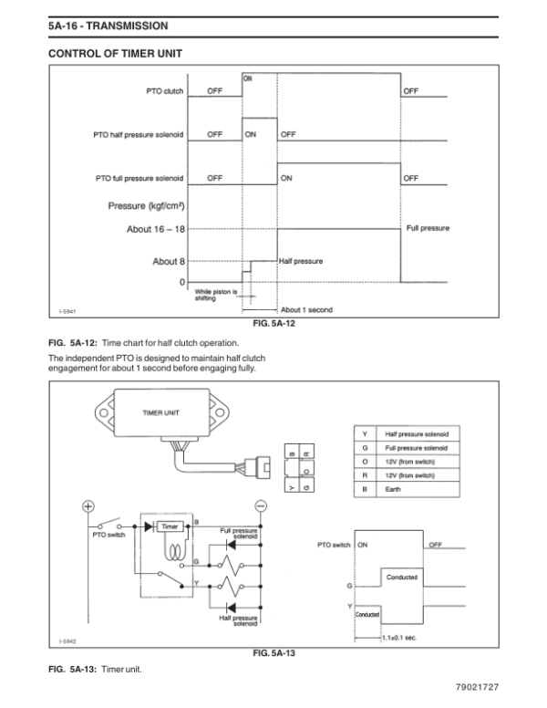
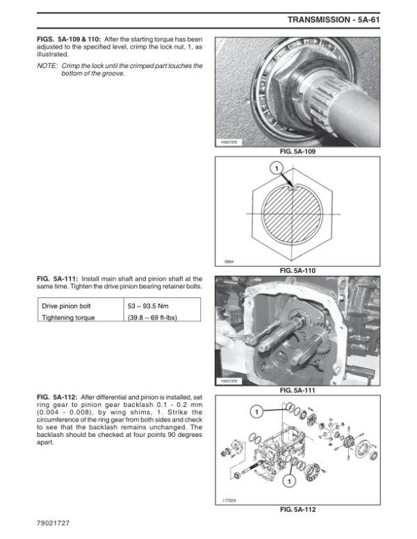
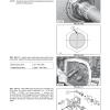
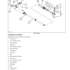
The transmission chapter provides workshop information on mechanical shuttle controls, forward/reverse synchronizer components, input shafts, main transmission gears, range gears and differential assemblies. Separate sections address PTO solenoid operation, the timer relay, PTO clutch inspection, rear and mid PTO components, and the front-wheel shift mechanism. These references help identify the appropriate procedure for transmission and PTO maintenance.
The hydraulic documentation includes pump servicing, flow and pressure checks, three-point linkage adjustments, hydraulic cylinder maintenance, main control valves, relief valves and optional draft control equipment. The electrical section provides information about the battery, instrument panel, gauges, switches, wiring harnesses, relays, diodes and troubleshooting. Check the tractor’s installed equipment and the applicable section before beginning service work.



























Reviews
There are no reviews yet.