Transmission, PTO Clutch and Drivetrain Servicing
The transmission chapter provides technical information on input gears, PTO clutch construction and oil supply, reducing valve operation, PTO solenoid controls and timer relay components. The PTO drive system section includes gear train diagrams, range shift positions, PTO drive arrangements and servicing references for the mid power take-off assembly.
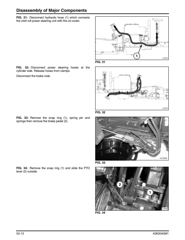
Additional procedures address removal and installation of the hydrostatic transmission unit, range change section and mid PTO components. The tractor splitting chapter provides separate procedures for removing major components and separating the engine, transmission cases, rear axle housing and steering unit.
Hydrostatic Transmission Inspection and Pressure Testing
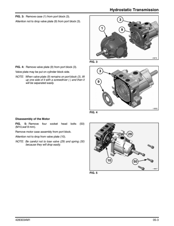
The hydrostatic transmission documentation identifies the major components of the hydrostat pump and motor assemblies. It contains procedures for disassembling the pump, motor, cylinder block, shafts and port block, along with criteria for assessing worn components and determining when replacement is necessary.
Reassembly information includes installation of the pump shaft, motor shaft, cylinder block, slant board, port block and housing components. The hydrostat testing procedure provides specific references for charge pressure checking and high-pressure relief testing, allowing technicians to consult the appropriate inspection and diagnostic instructions.
Front Axle, Rear Axle and Brake Maintenance
The front axle section provides construction information, disassembly procedures, component inspection, reassembly precautions and troubleshooting guidance. It includes references to differential components within the axle disassembly documentation.
Rear axle servicing covers the axle housing, brake-related components, final reduction gears and wheel shaft assemblies. The chapter also includes brake adjustment procedures and inspection references for evaluating axle and braking components during workshop maintenance.
Hydraulic System, Control Valves and Gear Pump Repairs
The hydraulic chapter provides system specifications, hydraulic circuit diagrams and servicing information for the main hydraulic components. Its main control valve section describes valve construction and operation, including the main spool, compensator, check valve and neutral, raising and lowering positions.
Further technical references cover the flow control valve, safety valve, relief valve and hydraulic gear pump. Procedures include relief valve cracking-pressure measurement, pump disassembly, component inspection and reassembly. The hydraulic troubleshooting section provides additional guidance for investigating system performance problems.
Selecting the Correct Service Procedure
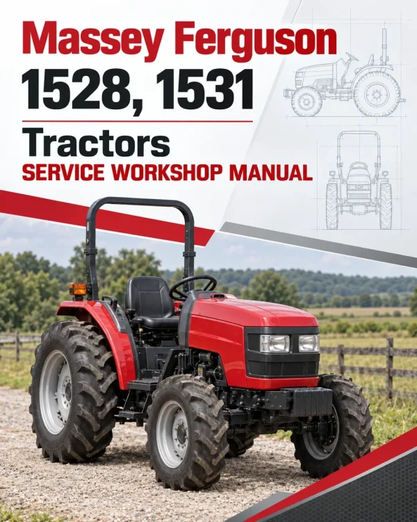
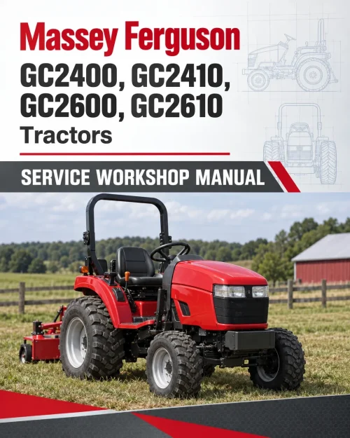
Before performing repairs on the Massey Ferguson 1528 or 1531, identify the tractor model and the assembly requiring service. Consult the relevant transmission, hydrostatic drive, axle or hydraulic system chapter for component specifications, removal procedures, inspection requirements and reassembly instructions.
For work involving multiple tractor assemblies, refer to the splitting procedures before removing the engine, transmission sections, rear axle housing or power steering unit. Follow the applicable service instructions and component specifications when completing adjustments and repairs.



















Reviews
There are no reviews yet.