Overview
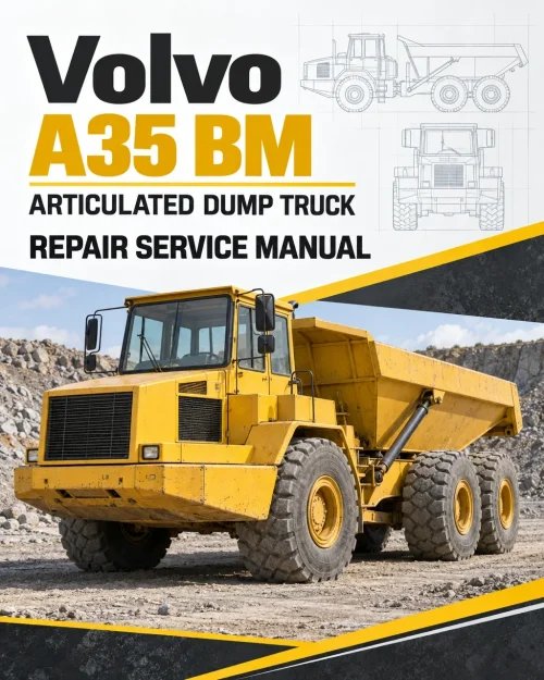
The Volvo A25 6×4 BM Articulated Dump Truck Service Repair Manual provides a workshop reference for maintaining, diagnosing and repairing the documented machine systems. The contents bring together braking equipment, steering components, working and servo hydraulics, and electrical and instrument systems.
Component-level coverage extends to hydraulic transmission controls, transfer gearbox components, dry-brake components, parking-brake components, and cooling-system components.
Table of Contents
Volvo A25 6×4 BM Manual
-
01. General
- Specifications
- Tool — Instructions for checking control unit with ZF test instrument model PR-61 (1 PO1 137 304)
-
02. Standard Parts, Service
- Service — General, common info about 171 – 179
- Service — Emergency measures
- Safety equipment, without own function group
-
03. Engine with Mounting and Equipment
- General, engine installation and its function
- Engine — General, common info about 211 – 218
- Engine — Cylinder head
- Engine — Valve mechanism
- Engine mounting
- Lubricating System — General, common info about 221 – 224
- Fuel System — Fuel pump; filter; strainer
- Fuel System — Fuel tank; fuel filling pump
- Fuel System — Injection pump; regulator; pump companion
- Fuel System — Injector; delivery pipe
- Inlet System; Exhaust System — Turbo charger
- Inlet System; Exhaust System — Air cleaner with connections; air pre-heater
- Cooling System — General, common info about 261 – 269
- Cooling System — Radiator, mounting and connections included
- Cooling System — Fan; fan shroud; fan coupling
-
04. Elec. System; Warning System; Information System; Instruments
- Comprehensive info, electrical system
- Battery; Energy Storage System; Mounting Parts — Battery
- Alternator; Charging; Electric Motor; Electric Drives — Alternator inclusive drive
- Alternator; Charging; Electric Motor; Electric Drives — Charging; converter
- Starting System — General, common info about 331 – 334
- Starting System — Starter motor inclusive solenoid
- Lighting — General, common info about 351 – 356
- Lighting, front, including parking light and day running light
- Cable; Fuse; Relay — General, common info about 371 – 379
- Cable; Fuse; Relay — Cable; battery disconnector
- Cable; Fuse; Relay — Electrical distribution box; fuse box; junction box
- Instrument; Sensor; Warning and Information System — General, common info about 383 – 387
- Instrument; Sensor; Warning and Information System — Sender, monitoring system
-
05. Power Transmission
- General, common info about 410 – 436
- Clutch; Torque Converter — Hydrodynamic coupling, torque converter
- Transmission, hydraulic control
- Gearbox — Distributing gearbox
- Propeller Shaft — General, common info about 451 – 453
- Propeller shaft, complete
- Front Axle; Rear Axle — General, common info about 461 – 468
- Front Axle; Rear Axle — Differential lock, with control — Transverse differential lock, checking and adjusting (Applicable for all axles)
- Power take off, between engine and gearbox (ART)
-
06. Brake
- Comprehensive info about brakes
- Wheel Brake — General, common info about 511 – 519
- Wheel Brake — Front wheel brake, dry brake
- Hydraulic Brake System — General, common info about 520 – 522
- Parking Brake — General, common info about 551 – 554
- Parking Brake — Brake control, mechanical
- Parking Brake — Propeller shaft brake
- Compressed-air Brake — General, common info about 561 – 565
- Compressed-air Brake — Compressor; regulator; antifreeze unit
- Compressed-air Brake — Compressed-air tank, with mounting
- Compressed-air Brake — Valves, compressed-air
-
07. Steering
- Comprehensive info, steering
- Steering gear
- Steering arm; steering linkage; track rod
- Hydraulic equipment
- Supplementary steering
-
08. Frame; Springs; Damping; Axle Suspension; Wheel/track Unit
- Frame — General, common info about 711 – 718
- Frame, complete
- Suspension — General, common info about 725 – 727
- Suspension — Hollow rubber spring, bump stop
- Frame Link — General, frame link complete
- Frame Link — Bearings
- Axle Suspension — Suspension, front axle
- Axle Suspension — Bogie suspension
- Wheels; Tracks; Tyre; Hub; Drum — Wheel
- Wheels; Tracks; Tyre; Hub; Drum — Spacers; stone protection ring; fastener
-
09. Machinery House; Cab; Exterior Trim Parts Anywhere
- Cab, Naked; Canopy
- Trim Part, Outside; Glass; Sealing Moulding — Glass; sealing moulding
-
10. Hydraulic System; Digging/ Handling/ Grading Equipm.; Misc. Equip.
- Working Hydraulics; Servo Hydraulics — General, common info about 911 – 917 — Hydraulic system-diagram and position of components, 4 x 4 w.e.fr. ser. no. 4066–
- Working Hydraulics; Servo Hydraulics — Tank; line; oil cooling; filter; breather; filling pump
- Working Hydraulics; Servo Hydraulics — Working hydraulics — Tipping control cable, fitting and adjusting, 4 x 4 up to ser. no. –4065
- Working Hydraulics; Servo Hydraulics — Pump, working hydraulics
- Load Carrier — Hauler/platform body, incl. tipping cylinder; heating; tail gate — Hydraulic cylinders, changing piston rod seals (using SVO 3579B and SVO 3597)
Tipping Controls and Hydraulic Diagrams by Serial Range
This coverage includes the entries “Hydraulic system-diagram and position of components, 4 x 4 w.e.fr. ser. no. 4066–” and “Tipping control cable, fitting and adjusting, 4 x 4 up to ser. no. –4065”.
Where similar entries are repeated, select the one carrying the appropriate serial qualifier. A range shown for one component should not be generalized to the complete manual.


























Reviews
There are no reviews yet.