Overview
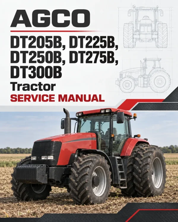
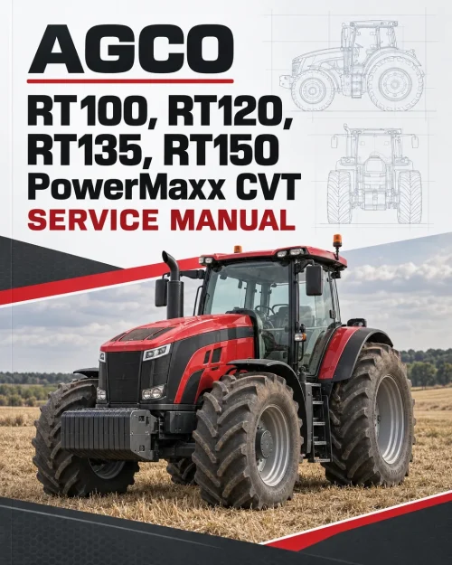
The AGCO DT205B, DT225B, DT250B, DT275B, and DT300B Tractor Service Manual provides detailed technical information for agricultural tractor maintenance, troubleshooting, inspection, adjustment, and component repair. The workshop documentation covers SisuDiesel engine systems, PowerMaxx continuously variable transmissions, rear and front axles, power take-off assemblies, load-sensing hydraulics, electrical equipment, electronic controls, cab systems, and specialised service procedures.
The service documentation includes tractor component separation, engine disassembly and reassembly, transmission hydraulic testing, differential and braking system repairs, and electronic fault diagnosis. Detailed sections address ML260 gearbox servicing, HA260 rear axle components, DANA770 front axles, hydraulic linkage controls, electronic calibrations, cab suspension, and air conditioning, supported by wiring diagrams, diagnostic codes, hydraulic schematics, and service tool information.
Notice: The documentation identifies different engine emission configurations, including SisuDiesel Tier 3 and e3 SCR Technology systems, together with optional front axle, hydraulic, electronic, and cab equipment. Select the procedures and specifications corresponding to the tractor’s engine configuration and installed components.
Table of Contents
AGCO DT205B, DT225B, DT250B, DT275B, DT300B Manual
- 01. Introduction
- General tractor information and specifications
- PowerMaxx CVT and Stepshift operating speeds
- Machine dimensions, weights and attachment points
- Fluid capacities and accumulator specifications
- Instrument panel indicators and error codes
- Engine and transmission diagnostic codes
- Four-wheel-drive and differential lock fault codes
- PTO, ParkLock and suspended axle diagnostics
- Electrical fuse boxes and circuit diagrams
- Electrical connector and wiring harness identification
- Transmission and auxiliary hydraulic schematics
- Steering, braking and linkage hydraulic circuits
- Valve clearance adjustment
- Fuel, clutch and brake system bleeding
- Forward-speed and throttle pedal calibration
- Transmission, PTO and linkage calibration procedures
- 02. Separation of Assemblies
- Front side member disassembly and reassembly
- Side member removal without removing the engine
- Front axle removal and installation
- Engine removal and reinstallation
- Engine flywheel spacer servicing
- Hydraulic spacer removal and installation
- Rear axle and gearbox separation
- Cab removal and reinstallation
- Rear auxiliary hydraulic unit removal
- Complete hydraulic unit and pipe assembly
- Front linkage removal and installation
- 03. Engine
- SisuDiesel Tier 3 engine specifications
- Engine construction and operating principles
- Lubrication and cooling systems
- Air intake, exhaust and fuel systems
- Common Rail electronic fuel injection
- Engine electrical control circuits
- Engine error codes and diagnostic procedures
- Fuel supply and engine oil pressure testing
- Valve clearance and throttle pedal adjustments
- Fuel system bleeding
- Cylinder block and cylinder head servicing
- Crankshaft, connecting rods and pistons
- Valve mechanism and timing housing
- Engine lubrication and cooling component repairs
- Fuel injection pump and injector servicing
- e3 SCR Technology engine operation
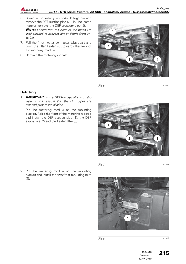
- Diesel exhaust fluid system components
- SCR metering module and injector
- SCR catalyst and associated components
- Engine disassembly and reassembly
- 04. Clutch
- 05. Gearbox
- ML260 transmission general information
- PowerMaxx CVT operating principles
- Transmission hydraulic circuit diagrams
- Transmission electrical system diagnostics
- Gearbox component locations and identification
- Transmission accumulator pressure testing
- Supply pressure and high-pressure measurements
- Transmission shifting pressure testing
- Hydrostatic transmission circuit inspection
- Forward and reverse pressure relief valves
- Transmission flushing valve and control spool valve
- Forward-speed calibration
- Throttle pedal and armrest lever calibration
- Transmission high/low range calibration
- Clutch control bleeding
- Transmission oil filling procedures
- PowerMaxx CVT disassembly and assembly
- Clutch control disassembly and reassembly
- Gearbox servicing and special tools
- 06. Rear Axle
- HA260 rear axle construction and operation
- Rear axle component layouts and diagrams
- Final drive unit removal and installation
- Final drive disassembly and reassembly
- Rear axle differential servicing
- Differential and pinion removal and installation
- Differential lock testing and calibration
- Tractor braking system operation
- Brake accumulator testing
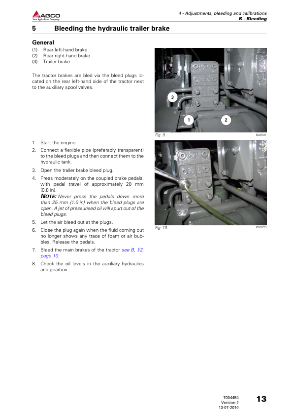
- Brake system bleeding
- Brake unit and high-pressure valve servicing
- Brake disc and pedal sensor replacement
- ParkLock system diagnosis and repair
- Hydraulic trailer braking systems
- Pneumatic trailer braking systems
- Auto-hitch adjustment and servicing
- Rear wheel and hub adjustments
- Rear wheel track width and tightening torques
- 07. Power Take-Off
- HA260 rear PTO system construction
- Power take-off operating principles
- Power take-off error codes
- Rear PTO hydraulic and electrical circuits
- HA260 and HA260F PTO components
- PTO supply and shifting pressure testing
- PTO solenoid valve testing
- Rear PTO disassembly and reassembly
- Zuidberg front power take-off
- Front PTO hydraulic and electrical testing
- Front PTO removal and installation
- Front PTO shaft servicing
- Front PTO disassembly and reassembly
- 08. Front Axle
- DANA770 front axle specifications
- Fixed and suspended front axle configurations
- Front axle component identification
- Front axle lubrication and tightening torques
- Suspended front axle fault diagnosis
- Accumulator pressure and hydraulic testing
- Suspended front axle calibration
- Front axle tightening torques and preloads
- Front transmission shaft servicing
- Four-wheel-drive shaft bearing replacement
- Four-wheel-drive clutch construction
- 4WD clutch hydraulic pressure testing
- 4WD clutch disassembly and repair
- Steering unit construction and operation
- Steering hydraulic system testing
- Orbitrol steering unit servicing
- Steering column disassembly and reassembly
- 09. Hydraulics
- Load-sensing hydraulic system operation
- Hydraulic circuit and component diagrams
- Hydraulic accumulator pressure testing
- Load-sensing hydraulic pump operation
- Hydraulic pump removal and installation
- Auxiliary spool valve construction
- Auxiliary hydraulic valve diagnostics
- Auxiliary spool valve removal and installation
- Hydraulic coupler servicing
- Rear hydraulic linkage operation
- Rear linkage calibration and adjustment
- Rear linkage spool valve servicing
- Front hydraulic linkage operation
- Front linkage position sensor adjustment
- Front linkage cylinder and spool valve repair
- Front linkage folding cylinder servicing
- Hydraulic component testing and troubleshooting
- 10. Electrical System
- Electrical system operating principles
- Electrical circuit diagrams
- Lighting system and component locations
- Fuse box construction and servicing
- Fuse board removal and installation
- Alternator electrical system
- Alternator testing and component inspection
- Alternator removal and installation
- Fan, alternator and air conditioning drive belts
- Battery electrical circuits
- Starter motor operation and diagnostics
- Starter removal and installation
- Battery isolator construction and operation
- 11. Electronics
- Automatic air conditioning electronics
- Power take-off electronic controls
- Engine electronic functions and diagnostics
- Transmission electronic controls
- ParkLock electronic operation and diagnostics
- Four-wheel-drive electronic functions
- Differential lock electronic controls
- Headlight module diagnostics
- Suspended front axle electronic functions
- Suspended cab electronic functions
- Auxiliary hydraulic electronic controls
- Electronic linkage functions
- Vistronic cooling fan control
- SpeedSteer electronic functions
- Isobus electrical circuits
- Auto-Guide error codes and diagrams
- Telemetry system operation
- AGCOMMAND telemetry components
- Telemetry programming and parameter settings
- 12. Cab
- Standard air conditioning system
- Air conditioning component identification
- Compressor and refrigeration system servicing
- Air conditioning pressure and leak testing
- Air conditioning drive belt servicing
- Refrigerant system draining and refilling
- Cab roof removal and installation
- Evaporator, heater radiator and fan servicing
- Self-regulating air conditioning system
- Automatic climate control diagnostics
- Passive hydraulic cab suspension
- Semi-active hydraulic cab suspension
- Passive pneumatic cab suspension
- Semi-active pneumatic cab suspension
- Cab suspension pressure and leakage testing
- Suspension cylinder and shock absorber servicing
- Reverse station operation and components
- Reverse station removal and reassembly
- 13. Accessories
- Front-end loader electrical and hydraulic diagrams
- 14. Service Tools
- General special service tool information
- SisuDiesel Tier 3 engine service tools
- e3 SCR Technology engine service tools
- ML260 gearbox service tools
- HA260 rear axle and final drive tools
- Differential and braking system tools
- ParkLock and trailer brake service tools
- Power take-off service tools
- DANA770 front axle service tools
- Load-sensing hydraulic system tools
- Hydraulic linkage and spool valve tools
- Alternator service tools
- Air conditioning service tools
Forward-Speed Calibration and Instrument Panel Settings
The workshop documentation includes a forward-speed calibration procedure designed to improve the accuracy of the tractor’s speed indication when different tyre sizes are fitted or when an optional radar speed sensor is installed. Calibration uses a measured course of 100 metres (328 feet), with the instrument panel display selector used to enter calibration mode and record the tractor’s movement over the measured distance.
The tractor must already be moving at normal working speed before crossing the starting line of the measured course. During calibration, the instrument panel displays the calibration and running indications, allowing the operator to register the start and finish points. The completed procedure provides the calculated theoretical forward speed and, on tractors equipped with radar, the corresponding actual radar-measured speed. The display selector then returns the instrument panel to its normal operating mode.

















Reviews
There are no reviews yet.