Overview
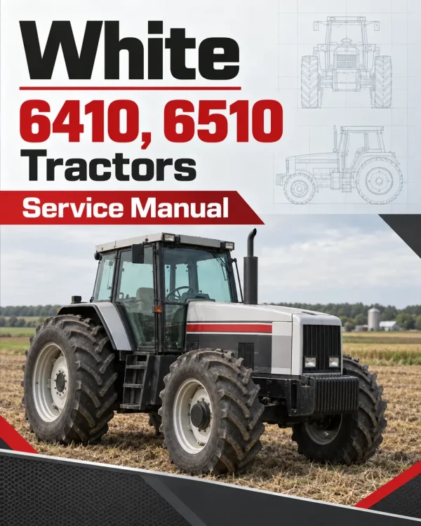
The White 6410 and 6510 Tractor Service Manual provides detailed technical information for tractor maintenance, troubleshooting, inspection, adjustment, and component repair. The workshop documentation covers engine systems, oil-cooled clutch, mechanical gearboxes, rear and front axles, power take-off, hydraulics, electrical equipment, electronic controls, and cab components.
The service documentation includes technical specifications, tractor separation procedures, transmission servicing, braking system maintenance, hydraulic component repairs, and electrical wiring diagrams. Additional sections cover cooling and fuel systems, electronic lift control, air conditioning, and specialised service tools to support the inspection, disassembly, repair, and reassembly of applicable tractor components.
Table of Contents
White 6410, 6510 Manual
- 01. Introduction and General Information
- General specifications
- Safety information and servicing notes
- General maintenance information
- 02. Splitting the Tractor
- 03. Engine
- Engine specifications
- Cooling system
- Fuel system
- Air system
- 04. Clutch
- 05. Gearbox
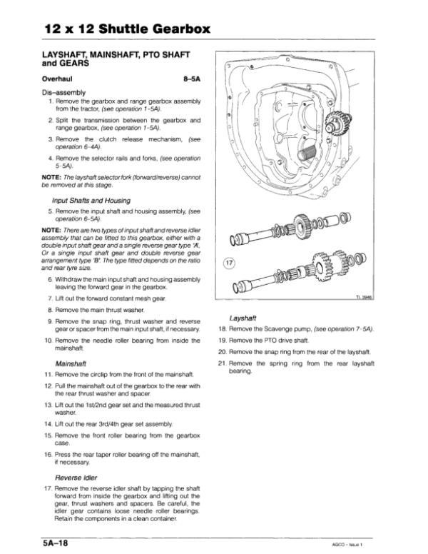
- 12 × 12 shuttle gearbox
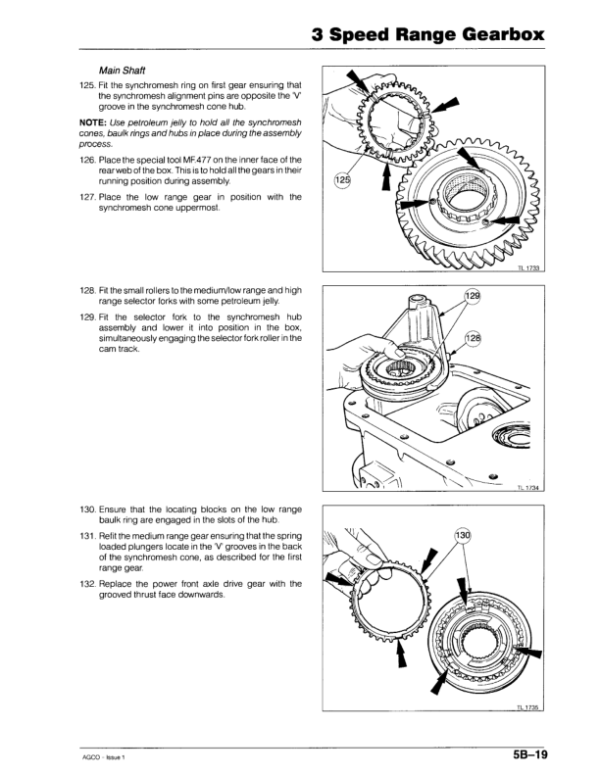
- Three-speed range gearbox
- 12 × 4 manual gearbox
- Two-speed range gearbox
- Power front axle drive shaft
- 06. Rear Axle
- Braking system
- Crown wheel and pinion
- Rear axle assembly
- Drawbar and three-point linkage
- Wheels and tyres
- 07. Power Take-Off
- 08. Front Axle
- Two-wheel-drive front axle
- Power front axle
- 09. Hydraulics
- Oil supply control valve
- Control valve disassembly
- Valve component examination
- Valve spindle, spring and washer
- O-ring and wiper seal replacement
- 10. Electrical System
- Electrical system
- Cab wiring diagrams
- 11. Electronics
- Speedometer
- Electronic lift control
- 12. Cab and Sheet Metal
- Cab
- Sheet metal
- Air conditioning
- 13. Accessories
- 14. Service Tools
Oil Supply Control Valve Servicing
The hydraulic servicing instructions describe disassembly of the oil supply control valve, beginning with disconnection of the hydraulic hoses and removal of the clevis pin connecting the cylinder to the operating lever. The procedure continues with removal of the spring clip, cylinder assembly, retaining circlip, and internal valve components, including the spindle, spring, washer, and valve.
During examination, the disassembled components are cleaned and inspected for wear, with particular attention to the valve seating surfaces in the cylinder and on the spindle. The valve must move freely along its spindle, and worn components are replaced as necessary. The procedure also identifies the internal O-rings and wiper seal for removal and replacement during servicing.













Reviews
There are no reviews yet.