Overview
The AGCO ST34A and ST41A Tractor Repair Service Manual provides detailed technical information for compact tractor maintenance, troubleshooting, inspection, adjustment, and component repair. The workshop documentation covers engine systems, major component separation, clutch assemblies, mechanical and hydrostatic transmissions, front and rear axles, hydraulic systems, electrical equipment, power steering, and cab air conditioning.
The service documentation includes illustrated component removal and installation procedures, transmission servicing, hydraulic circuit testing, brake adjustments, electrical wiring diagrams, and mechanical troubleshooting. Detailed sections address Power Shuttle systems, hydrostatic transmission controls, four-wheel-drive components, hydraulic valves, steering assemblies, and air conditioning maintenance, with technical specifications and inspection procedures supporting accurate component repairs.
Notice: The documentation covers different transmission configurations, including Synchro Shuttle, Power Shuttle, Power Shift, and hydrostatic systems. Select the applicable servicing procedures according to the transmission and equipment fitted to the tractor.
Table of Contents
AGCO ST34A, ST41A Manual
- 01. General Information
- 02. Engine Service Manual
- 03. Engine
- Engine cooling system
- Radiator, fan belt and thermostat servicing
- Radiator inspection and leak testing
- Coolant reservoir system
- Water pump removal and installation
- Fuel system and fuel filter
- Fuel pump and fuel system air bleeding
- Engine air cleaner servicing
- 04. Major Components
- Major component disassembly and assembly
- Service access and component removal
- Front axle removal
- Engine and transmission housing separation
- Engine removal
- Hydrostatic transmission bell housing separation
- Front and rear transmission case separation
- Rear axle and lift cylinder case removal
- Platform and cab removal
- Chassis components and three-point linkage
- 05. Clutch
- Transmission clutch construction
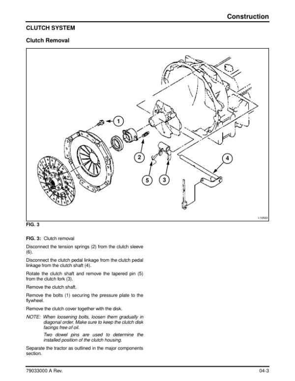
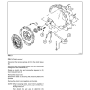
- Clutch removal and inspection
- Clutch disc and cover assembly
- Clutch assembly procedures
- Release bearing servicing
- Clutch cross shaft
- Clutch free-play adjustment
- Clutch troubleshooting
- 06. Transmission
- Standard and Power Shuttle transmissions
- Transmission powertrain and gear ratios
- Shuttle clutch and clutch pack servicing
- Input gears and input housing
- Main transmission gears and shift lever
- Range gears and shift linkage
- Rear power take-off and PTO clutch
- Mid PTO construction and linkage
- Four-wheel-drive gears and shift mechanism
- 07. Hydrostatic Transmission
- Hydrostatic transmission operation
- Hydrostat unit specifications
- HST testing procedures
- Hydrostat disassembly, inspection and assembly
- HST unit installation
- Hydrostatic oil cooler and filter
- Hydrostatic transmission troubleshooting
- Single-pedal HST control mechanism
- HST pedal and cruise control adjustments
- Two-pedal HST linkage mechanism
- 08. Rear Axle and Brakes
- Rear axle construction and specifications
- Rear axle assembly procedures
- Rear wheel shaft and oil seal servicing
- Brake system inspection and adjustment
- Differential lock mechanism
- Rear axle differential servicing
- Brake and differential assembly
- Brake troubleshooting
- 09. Front Axle
- Four-wheel-drive front axle construction
- Front axle specifications
- Front-wheel-drive shaft servicing
- Front differential disassembly and inspection
- Pinion carrier and differential gear servicing
- Front wheel final drive assemblies
- Front axle centre section
- Wheel shaft seals and axle bracket
- Final drive case servicing
- Front wheel alignment and toe-in adjustment
- Wheel spacing and steering free-play
- Front axle troubleshooting
- 10. Hydraulics
- Hydraulic system specifications and circuit diagrams
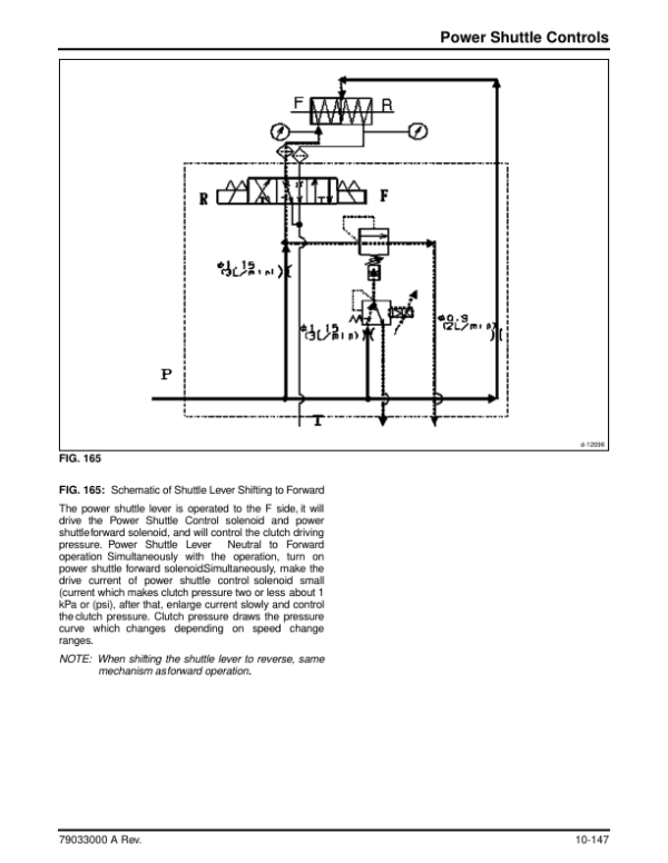
- Synchro Shuttle and Power Shuttle hydraulic systems
- Hydraulic component locations
- Hydraulic filters and gear pump
- Main relief valve and pressure control
- Hydrostatic transmission oil cooler and charge filter
- HST relief valve and hydraulic circuit
- Main hydraulic control valve
- Slow return and safety relief valves
- PTO and Power Shuttle control valves
- Joystick valve and front loader hydraulic couplers
- External auxiliary hydraulic system
- Hydraulic component assembly and maintenance
- Hydraulic control linkage adjustments
- Three-point lift linkage
- Hydraulic system troubleshooting
- 11. Electrical System
- Electrical wiring diagrams and colour charts
- Transmission-specific electrical circuits
- Cab electrical wiring diagrams
- Power Shuttle and PTO solenoid valves
- Solenoid valve resistance testing
- Instrument panel
- Electrical switches and relays
- Main wiring harness
- Power Shuttle electronic controls
- PTO electrical control system
- 12. Hydrostatic Steering
- Hydrostatic steering construction
- Major steering components
- Integral Orbitrol steering unit
- Steering unit disassembly and inspection
- Control and gerotor assembly procedures
- Flow control valve assembly
- Hydrostatic steering troubleshooting
- 13. Cab and Air Conditioning
- Cab roof and door servicing
- Door adjustment and locking mechanism
- Cab electrical equipment and wiring harness
- Air conditioning system construction
- Compressor and magnetic clutch
- Condenser and receiver dryer
- Expansion valve and pressure switches
- Air conditioner operation and control
- Air conditioning inspection and maintenance
- Air conditioner belt and refrigerant checks
- Compressor and condenser servicing
- Refrigerant evacuation and charging
- Air conditioning pressure testing and troubleshooting
Air Conditioning Operation and Compressor Pressure Protection
The cab air conditioning system uses a blower fan, magnetic compressor clutch, air outlet selector, and temperature-adjusting lever to control cabin conditions. With the engine running, activating the air conditioning switch energises the compressor clutch. The temperature control provides heating when moved toward the warm setting and cooling with dehumidification when the air conditioning system is activated and the lever is moved toward the cool setting.
The compressor incorporates high- and low-pressure protection switches that disengage the magnetic clutch when refrigerant pressure reaches the specified limits. The documented high-pressure cut-off is 3.14 MPa (455.42 psi), while the low-pressure cut-off is 0.2 MPa (29.01 psi). The workshop documentation also covers refrigerant level inspection, air conditioning component servicing, evacuation, charging, and troubleshooting procedures.

























Reviews
There are no reviews yet.