Overview
The Kubota KX018-4 Excavator Workshop Service Manual provides technical documentation for maintenance, troubleshooting, inspection and component repair of this Kubota compact excavator. The workshop reference covers machine identification, front attachments, undercarriage assemblies, engine specifications, hydraulic pumps, control valves, swivel and travel motors, hydraulic cylinders, electrical equipment and cabin components. Its mechanism and servicing sections provide component construction, operating principles, technical specifications, inspection, disassembly, assembly and repair information.
The documentation includes adjustable-track components, rubber crawler servicing, hydraulic pump horsepower control, straight-travel circuits, two-speed travel operation, pilot valves and hydraulic performance measurements. Electrical coverage provides starting-system checks, digital meter diagnostics, service dealer settings, CAN communication testing and individual fault-code references. The Cabin section addresses heater equipment, windshield wipers, lighting, glass installation and cabin removal, while General information includes maintenance intervals, tightening torques, component dimensions and regional servicing requirements.
Notice: The General section identifies separate maintenance requirements for North American and Australian configurations. The Cabin chapter documents heater and window equipment, while the Machine Body section also includes canopy servicing. Confirm the machine’s regional specification and installed equipment before selecting maintenance or component repair procedures.
Table of Contents
Kubota KX018-4 Manual
-
01. Information and Safety
- Safety First and Workshop Safety Instructions
- Safety Precautions Before Working on the Mini Excavator
- Safety Precautions Before Servicing Equipment
- Safety Label Locations
- Safety Label Maintenance
- Machine Technical Specifications
- Excavator Dimensions
-
02. General Information and Maintenance
- Machine Identification
- Engine Identification and Serial Number
- General Workshop Precautions
- Electrical Wiring Handling Precautions
- Fuse and Electrical Connector Precautions
- High-Pressure Washing Precautions
- General Fastener Tightening Torques
- Stud Bolt Tightening Torques
- Hydraulic Hose Fitting Tightening Torques
- Hydraulic Elbow and O-Ring Adaptor Torques
- Hose Clamp Tightening Specifications
- Oil and Water Capacity References
- Operator Maintenance Requirements
- Skilled Technician and Dealer Maintenance — North American Version
- Skilled Technician and Dealer Maintenance — Australian Version
- Bucket Specifications
- Bucket Installation Dimensions
- Dozer Blade Specifications
- Rubber Crawler Specifications
- Track Roller, Front Idler and Sprocket Information
- Hydraulic Cylinder Specifications
- Front Equipment Pin Identification
- Front Bushing Dimensions
- Component Weight References
- Component Quality Specifications
-
03. Machine Body — Inspection and Servicing
- Front Equipment Construction
- Bucket Installation and Removal
- Front Attachment Installation and Removal
- Dozer Blade Removal and Installation
- Swivel Frame Components
- Counterweight Disassembly and Assembly
- Canopy Removal and Installation
- Fuel Tank Removal and Installation
- Hydraulic Oil Tank Components
- Engine Removal and Installation
- Engine Mounting Components
- Engine Muffler
- Engine Supporting Structure
- Radiator and Hydraulic Oil Cooler
- Travel Operating Lever Assembly
- Dozer Blade Operating Lever Assembly
- Adjustable Track Operating Lever
- Blade and Adjustable Track Cable Routing
- Engine Accelerator Lever
- Accelerator Cable Routing
- Boom Swing Pedal
- Auxiliary Hydraulic Pedal
- Swivel Bearing Assembly
- Track Frame Assembly
- Rubber Track Disassembly and Assembly
- Front Idler Disassembly and Assembly
- Front Idler Components
- Track Frame Cylinder Assembly
- Track Roller Disassembly and Assembly
-
04. Engine — General Specifications
- Engine Technical Specifications
- Engine Performance Curves
- Engine Dimensions
-
05. Hydraulic System — Mechanism and Servicing
- Hydraulic System Circuit Diagram
- Hydraulic Component Layout
- Main Hydraulic Pump Specifications
- Hydraulic Pump Components
- Hydraulic Pump Operating Principles
- Hydraulic Pump Horsepower Control Mechanism
- Main Control Valve Specifications
- Main Control Valve Hydraulic Circuit
- Main Control Valve Construction and Operation
- Control Valve Internal Section Construction
- Straight Travel Hydraulic Circuit
- Travel Alarm Circuit
- Swivel Motor Specifications
- Swivel Motor Components and Operation
- Travel Motor Specifications
- Travel Motor Components and Operating Principles
- Travel Motor Counterbalance Mechanism
- Two-Speed Travel Motor Function
- Automatic Travel Deceleration Function
- Travel Motor Decelerator
- Boom Hydraulic Cylinder Construction
- Arm Hydraulic Cylinder Components
- Bucket Hydraulic Cylinder Components
- Boom Swing Hydraulic Cylinder Components
- Dozer Blade Hydraulic Cylinder Components
- Adjustable Track Hydraulic Cylinder Components
- Boom, Arm, Bucket and Swivel Pilot Valve
- Hydraulic Unload Valve
- Two Pattern Selection System (TPSS) Valve
- Hydraulic Pump Disassembly and Assembly
- Hydraulic Pump Component Service Standards
- Main Control Valve Removal and Installation
- Main Control Valve Disassembly and Assembly
- Swivel Motor Removal and Installation
- Swivel Motor Disassembly and Assembly
- Swivel Joint Removal and Installation
- Travel Motor Removal and Installation
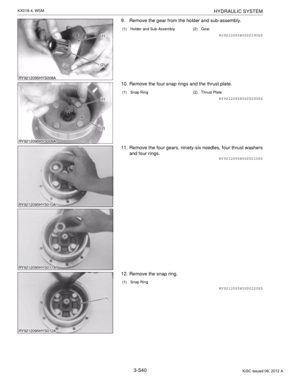
- Travel Motor Disassembly and Assembly
- Hydraulic Cylinder Disassembly and Assembly
- Pilot Control Valve Disassembly and Assembly
- Hydraulic Unload Valve Assembly
- Hydraulic Pressure Sensor Assembly
- Hydraulic Hose Specifications and Connection Types
- Hydraulic Delivery and Suction Hose Routing
- Hydraulic Delivery Hose Clamp Positions
- Front Equipment Hydraulic Hose Routing
- Travel Motor Hydraulic Hose Routing
- Swivel, Blade, Swing and Adjustable Track Hose Routing
- Track Frame Hydraulic Hose Routing
- Hydraulic Return Hose Routing
- Pilot Hydraulic Hose Routing
- Main Control Valve Pilot Hose Connections
- Pilot Hose Routing Around the Operator Seat
- TPSS Hydraulic Adaptor
- Hydraulic Component Performance Measurement
- Hydraulic System Troubleshooting
-
06. Electrical System and Electronic Diagnostics
- Electronic Equipment Layout
- Electrical Wiring Circuit
- Electrical Wiring Clamping Precautions
- Electrical Connector Handling Precautions
- Electrical Connector Disconnection and Wiring Layout
- Starting Equipment Troubleshooting
- Electrical Power and Ground Inspection
- Engine Starting and Stopping Device Inspection
- Meter Panel Controls and Functions
- Meter Panel Normal Operating Mode
- Meter Panel User Settings Mode
- Meter Panel Service Dealer Mode
- Service Dealer Diagnostic and Setting Functions
- Engine Oil Pressure Error — E:014
- Charging System Error — E:016
- Fuel Sensor Error — E:017
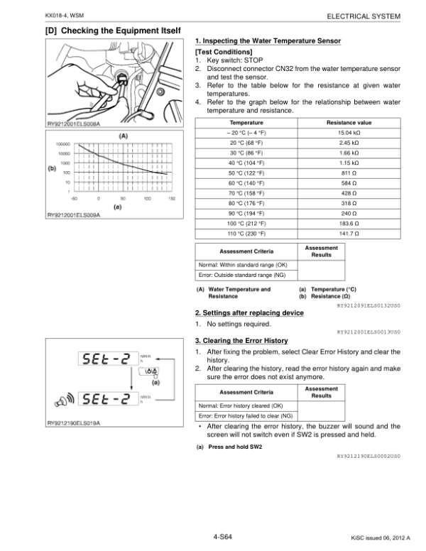
- Water Temperature Sensor Error — E:018
- Operating Lever Lock System Error — E:020
- Two-Speed Travel System Error — E:021
- Electrical Overvoltage Error — E:025
- External 5V Short-Circuit Error — E:027
- External 12V Short-Circuit Error — E:028
- CAN Communication Error — E:001
- Travel Alarm System Error
- Normal and User Settings Mode Flowcharts
- Service Dealer Mode Diagnostic Flowcharts
- Electrical Wiring Diagram
- Electrical Circuit Diagram
-
07. Cabin — Equipment and Servicing
- Cabin Removal and Installation
- Cabin Heater Removal and Installation
- Heater System Inspection
- Heater Blower Switch Inspection
- Heater Blower Motor Inspection
- Windshield Wiper Switch Testing
- Windshield Wiper Motor Inspection
- Window Washer Motor Inspection
- Cabin Lighting Equipment Inspection
- Cabin Glass Removal Preparation
- Window Glass Removal
- Window Glass Installation
- Window Glass Trim Types
- Cabin Component Troubleshooting
Adjustable Track Hydraulics and Two-Speed Travel Diagnostics
The workshop documentation covers the adjustable-track operating lever, hydraulic cylinder and associated hose routing, providing references for inspecting the machine’s track-width adjustment components. The hydraulic section also explains the travel motor counterbalance mechanism, two-speed operation and automatic deceleration function. When investigating travel performance or adjustable-track operation, use the applicable hydraulic circuit, component specifications and performance measurements before dismantling the affected assemblies.
The Electrical System chapter includes specific meter-panel fault codes for two-speed travel, lever locking, charging, engine sensors, power supply and CAN communication. These diagnostic references can help distinguish electrical control faults from hydraulic or mechanical problems. The cabin material is limited to the documented heater, window, wiper and lighting equipment; relevant procedures should be matched to the installed cabin configuration rather than assuming that every machine has the same equipment.




























Reviews
There are no reviews yet.