Overview
The Kubota KX61-3 and KX71-3 Excavator Workshop Service Manual provides technical documentation for maintenance, inspection, troubleshooting and component repair of these Kubota compact excavators. The workshop references cover machine identification, safety precautions, front attachments, upper structure, undercarriage, engine systems, hydraulics and electrical equipment. Mechanism and Service information explains component construction, operating principles, technical specifications, adjustment, disassembly and repair procedures for the applicable machine configurations.
The documentation includes bucket and swing-bracket servicing, crawler track maintenance, engine fuel-injection and cooling-system repairs, hydraulic pump and control-valve testing, swivel and travel motor servicing, and electrical fault diagnosis. The hydraulic sections provide pressure, flow and performance measurements, while the electrical references describe the Kubota Intelligent Control System (ICS), electronic service modes, controller self-diagnosis and wiring circuits. Separate technical information identifies European and PP configurations, including model-specific engine performance, hydraulic control valves, travel motors and Two Pattern Selection System (TPSS) components.
Safety: The General chapter identifies precautions for servicing, disassembly, reassembly and workshop lifting operations. It also specifies post-assembly inspections involving unusual noise, vibration, safety decals, wiring harness clamps and hydraulic oil level. Review the applicable instructions before performing component removal, hydraulic testing or machine reassembly.
Notice: Some hydraulic components, electrical circuits and service procedures differ between European and PP machine configurations. Confirm the applicable model and regional version before selecting technical specifications or adjustment procedures.
Table of Contents
Kubota KX61-3, KX71-3 Manual
-
01. General Information and Safety
- Machine Body Identification and Serial Number Plate
- Engine Serial Number Identification
- Workshop Safety Precautions Before Starting Work
- Safety Measures During Servicing and Disassembly
- Protective Equipment, Workshop Tools and Crane Operations
- Preparation for Component Disassembly and Reassembly
- Important Safety and Critical Functional Processes
- Essential Adhesives and Assembly Requirements
- Post-Assembly Noise and Vibration Inspection
- Safety Decal and Wiring Harness Clamp Inspection
- Hydraulic Oil Level Inspection After Reassembly
- Service Fundamentals — O-Rings, Oil Seals, Circlips and Roll Pins
- Hydraulic Piping and Hose Handling Precautions
- Hydraulic Hose Connections, Joint Bodies and Fittings
- Hose Clamp, Pipe and Fastener Tightening Torques
- Maintenance Intervals — European Version
- Maintenance Intervals — PP Version
- Hydraulic Oil Checks for Machines Equipped with Breakers
- Periodic Replacement of Important Components
- Machine Features and Model Configuration Differences
- Component Compatibility and Interchangeability
- Machine Weight, Specifications and Quality References
-
02. Machine Body — Mechanism and Servicing
- Machine Weight and Technical Specifications
- Machine Dimensions and Working Components
- Control Lever Stroke and Operating Force Specifications
- Front Attachment Pin and Bushing Service Limits
- Bucket Dimensions and Installation Measurements
- Rubber and Steel Crawler Specifications
- Track Rollers, Idlers, Drive Sprockets and Dozer Specifications
- Component Weights and Water/Oil Capacities
- Hydraulic Pump Coupling Arrangement
- Standard Bucket Construction and Installation
- Bucket Interchangeability and Replacement
- Bucket Tooth and Side Cutter Replacement
- Swing Bracket Construction and Components
- Swivel Bearing Assembly
- Front Attachment Dust Seal Installation Direction
- Swing Bracket Thrust Collar Installation
- Front Attachment Pin and Bushing Installation
- Grease Nipple Installation and Lubrication Points
- Travel Lever Assembly and Adjustment
- Accelerator Lever Assembly
- Dozer Lever and Swing Pedal
- Auxiliary Service-Port Pedal
- Control Valve Linkage and Pilot Lever Assembly
- Counterweight Assembly Reference
- Cab Removal and Installation
- Canopy Installation
- Cab Heater and Defroster Installation
- Thermal Insulation and Sound Absorber Installation
- Operator Seat and Seat Belt
- Cab Window Replacement
- Undercarriage Swivel Bearing and Grease Tube
- Track Idler and Tension Spring
- Track Tension Device
- Upper Roller and Track Roller Servicing
- Rubber Crawler Replacement
- Steel Crawler Components and Track Conversion
- Crawler Track Tension Adjustment
-
03. Engine — Mechanism and Servicing
- Engine Technical Specifications
- Engine Electrical Components
- V1505-E2-BH-9-EU Engine Performance — KX61-3 European Version
- V1505-E2-BH-10 Engine Performance — KX71-3 European and PP Versions
- Radiator Fan and Cooling Component Removal
- Radiator Assembly Servicing
- Engine Electrical Parts and Mounting Components
- Engine Air Cleaner and Muffler
- Hydraulic Pump Coupling
- Fuel Tank and Fuel Hose Removal
- Engine Removal and Reinstallation
- Engine Cylinder Block and Cylinder Head Construction
- Crankshaft, Piston and Piston Ring Mechanisms
- Connecting Rod, Rocker Arm and Camshaft
- Fuel Camshaft and Flywheel
- Engine Lubrication System
- Engine Oil Pump and Pressure Relief Valve
- Oil Filter Cartridge and Oil Pressure Switch
- Cooling System — Water Pump, Thermostat and Radiator
- Intake and Exhaust System Components
- Fuel Injection Pump and Injection Nozzles
- Engine Fuel Filter and Governor
- Automatic Advance Timer Reference
- Engine Charging System
- Engine Identification and General Service Precautions
- Engine Troubleshooting and Service Specifications
- Engine Maintenance Checklist and Tightening Torques
- Engine Body Checking and Adjustment
- Cylinder Head and Valve Disassembly and Assembly
- Engine Gear Case and Timing Gear Removal
- Piston and Connecting Rod Disassembly
- Flywheel and Crankshaft Disassembly
- Cylinder Head and Valve Servicing
- Timing Gear and Camshaft Inspection
- Piston, Connecting Rod and Crankshaft Servicing
- Cylinder Inspection and Servicing
- Engine Oil Pump Checking and Servicing
- Fan Belt and Radiator Inspection
- Fuel Injection Pump Checking and Adjustment
- Fuel Injection Nozzle Checking and Servicing
- Starter Motor and Glow Plug Inspection
- Starter and Alternator Disassembly and Servicing
-
04. Hydraulic System — Mechanism, Testing and Repair
- Hydraulic System Features and Operating Principles
- Hydraulic Circuit Diagram — KX61-3 European Version
- Hydraulic Circuit Diagram — KX71-3 European Version
- Hydraulic Circuit Diagram — KX71-3 PP Version
- Hydraulic Component Layout — PP Version
- Main Hydraulic Pump Construction
- Hydraulic Pump Pressure-Flow (P-Q) Performance Curve
- Main Pump Specifications — PVD-1B-28P-8G3-4575A
- Main Control Valve — European Configurations
- Main Control Valve — KX71-3 PP Configuration
- Control Valve Section Construction and Component Arrangement
- Pilot Valve — European Version
- Pilot Valve — KTC, KCL and KTA Versions
- Travel Motor Structure and Operating Circuit
- Swivel Motor Technical Specifications
- Swivel Motor Internal Components and Sectional Views
- Hydraulic Cylinder Dimensions and Specifications
- Rotary Joint (Swivel Joint)
- Unload Valve — North American and Oceania Versions
- Change Valve with Accumulator — European Version
- Two Pattern Selection System (TPSS) Valve
- Hydraulic Oil Cooler
- Pilot, Suction and Return Filters
- Hydraulic Check Valve
- Main and Overload Relief Valve Specifications
- Hydraulic Cylinder Operating Speed and Natural Fall Limits
- Common Hydraulic Circuit Troubleshooting
- Hydraulic Pump and Motor Fault Diagnosis
- Swivel System Performance Troubleshooting
- Travel System Performance Troubleshooting
- Hydraulic Pump Flow Measurement
- Pilot Pressure Testing
- Main Relief Valve Pressure Testing
- Overload Relief Valve Pressure Testing
- Swivel Brake Pressure and Release Valve Testing
- Travel Two-Speed Selector Pressure Testing
- Travel Motor Drain Flow Measurement
- Swivel Motor Drain Flow Measurement
- Swivel and Travel Motor Block Performance Testing
- Hydraulic Operating Speed Measurement
- Straight-Travel Performance Testing
- Hydraulic Cylinder Natural Fall Measurement
- Control and Travel Lever Operating Force Checks
- Control Lever Stroke Measurement
- Front Attachment Disassembly Preparation
- Hydraulic Pump Coupling and Pump Removal
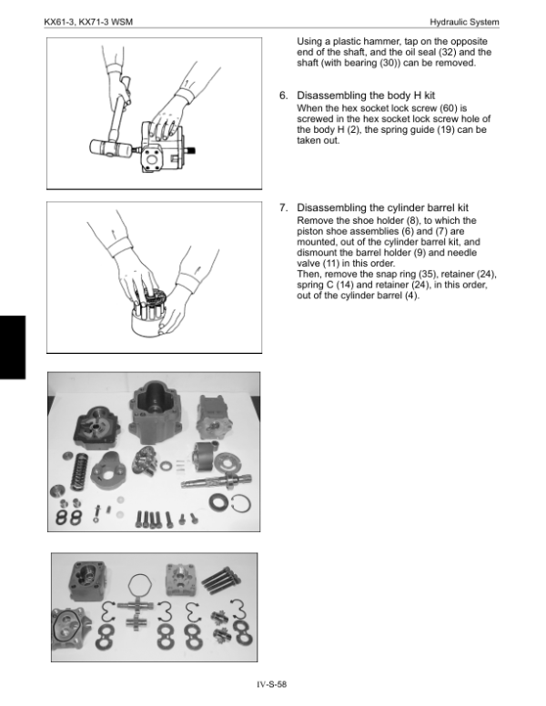
- Hydraulic Pump Disassembly and Reassembly
- Main Control Valve Removal and Installation
- Control Valve Disassembly and Reassembly
- Pilot Valve Removal and Disassembly
- Pilot Valve Troubleshooting and Servicing
- Swivel Motor Removal and Installation
- Swivel Motor Construction, Inspection and Repair
- Swivel Motor Disassembly and Reassembly
- Rotary Joint Disassembly and Servicing
- Travel Motor Servicing — KX71-3 PP Version
- Travel Motor Disassembly and Reassembly
- Hydraulic Cylinder Disassembly and Assembly
- Pilot Filter and Change Valve Servicing
- TPSS Valve Servicing — KX71-3 PP Version
- Hydraulic Oil Tank Servicing
- Pilot Hydraulic Hose Installation
- High-Pressure Hydraulic Hose Connections
- Low-Pressure Hydraulic Hose Connections
-
05. Electrical System and Kubota ICS Diagnostics
- Electrical System Specifications
- Electrical System Development and Meter Features
- Model-Specific Electrical Function Comparisons
- Kubota Intelligent Control System (ICS) Overview
- ICS Operating Modes
- LCD Display Information and Functions
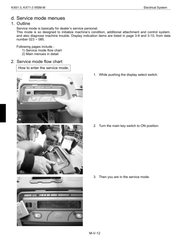
- ICS Service Mode Menus
- Service Mode Flowcharts and Menu Functions
- Electronic Failure Display and Diagnostic Criteria
- Failure Records Stored in EEPROM
- Electronic Controller Self-Diagnosis
- Electrical Component Layouts
- Service Mode Reference — Non-AI and Non-Anti-Theft Configurations
- Electrical Wiring Diagrams — European and Export Versions
- Wire Harness and Connector Identification
- Electrical Circuit Diagrams
- Engine Electrical Troubleshooting
- Meter Panel Fault Diagnosis
- Electrical Component Testing
- Wiring Harness Installation Precautions
- Engine Ground and Starter Switch Connections
- Battery Inspection and Connections
- Limit Switch Wiring and Testing
- Electrical Wiring Harness Routing
Engine Variants, Hydraulic Components and Electronic Service Modes
The engine mechanism documentation identifies different V1505-E2 configurations in its performance references, with the European KX61-3 using the V1505-E2-BH-9-EU reference and the KX71-3 using V1505-E2-BH-10 references for the documented European and PP variants. These distinctions are relevant when comparing engine performance information, component arrangements and the applicable workshop procedures. The incorporated engine service section also provides detailed inspection and repair references for internal engine components, fuel injection equipment, lubrication and cooling systems.
Hydraulic servicing distinguishes regional control-valve arrangements and identifies specific travel motor and TPSS procedures for the KX71-3 PP configuration. Pressure, flow, motor drain and cylinder performance measurements should be evaluated using the corresponding configuration’s specifications. The electrical mechanism reference includes Kubota ICS operating and service modes, stored fault records and controller self-diagnosis, with a separately identified service-mode reference for configurations without Auto Idle and anti-theft functions.




























Reviews
There are no reviews yet.