Overview
The Kubota U17 and U17-3 Excavator Workshop Service Manual provides technical documentation for maintenance, inspection, troubleshooting and component repair of these Kubota compact excavators. The workshop reference covers machine identification, safety precautions, service schedules, machine-body construction, front attachments, undercarriage assemblies, engine systems, hydraulics and electrical equipment. Separate mechanism and servicing sections describe component operation, technical specifications, inspection procedures, adjustment, disassembly and reassembly.
The documentation includes hydraulic pump and control valve servicing, swivel and travel motor testing, hydraulic pressure and flow measurements, service-port operation, and the Kubota Intelligent Control System (KICS). Engine references cover emissions-control features, engine accessories and the incorporated SM-E3B Series workshop section. The electrical chapters provide diagnostic menus, alarm displays, Auto Idling controls, wiring diagrams and component testing. Regional information distinguishes EU, PP (KTC/KCL) and KTA configurations, while additional references identify U17-3a model changes and equipment variations.
Safety: Review the safety precautions for servicing, disassembly and reassembly before performing workshop operations. The manual identifies important safety and critical functional processes, post-reassembly inspections and precautions for hydraulic piping and related components. Follow the applicable lifting, hydraulic testing and component handling instructions.
Important Information: Maintenance schedules, hydraulic circuits and certain electrical and control-system procedures differ by regional version and machine configuration. The documentation also references the U17-3a when describing model changes and component layouts. Select the specifications and procedures corresponding to the machine identification and installed equipment.
Table of Contents
Kubota U17, U17-3 Manual
-
01. General Information, Safety and Maintenance
- Machine Body and Engine Identification Marks
- Workshop Safety Precautions Before and During Servicing
- Preparation for Disassembly and Reassembly
- Important Safety Processes and Critical Functional Procedures
- Post-Reassembly Inspection and Hydraulic Piping Checks
- Maintenance Intervals — European Version
- Maintenance Intervals — PP (KTC/KCL) Version
- Maintenance Intervals — KTA Version
- Hydraulic Oil Checks for Machines with Hydraulic Breakers
- Maintenance Items and Operator Troubleshooting
- Periodic Replacement of Important Components
- Recommended Oils and Lubricants
- Excavator Lifting Capacity
- U17, U17-3 and U17-3a Model Development References
- Model Changes, Features and Specification Comparisons
-
02. Machine Body — Mechanism and Servicing
- Machine Specifications and Working Range
- Machine Dimensions with Rubber Crawlers
- U17-3a and U17/U17-3 Configuration Differences
- Machine Body Arrangement and Undercarriage Components
- Machine Weight, Lever Stroke and Operating Force Specifications
- Component Dimensions and Quality Specifications
- Front Attachment Pin, Bushing and Shim Installation
- Bushing Press-Fitting Instructions
- Front Attachment Greasing Points
- Upper Structure Swivel Bearing
- Travel Lever and Accelerator Lever Assemblies
- Dozer Lever and Swing Pedal
- Auxiliary Service-Port Pedal
- Pilot Control Valve and Limit Switch Installation
- Operator Seat, Seat Belt and Wrist Rest
- Canopy and Counterweight Installation
- Undercarriage Track Tension Device
- Track Roller Inspection and Installation
-
03. Engine — Mechanism and Servicing
- Engine Technical Specifications
- Emissions-Control Engine Features and Model Changes
- Engine Mounting and Accessories
- Air Cleaner Assembly
- Radiator and Cooling Components
- Thermostat and Muffler
- Engine Pump Coupling
- Fuel Tank and Fuel Hose Installation
- Engine Component Arrangement
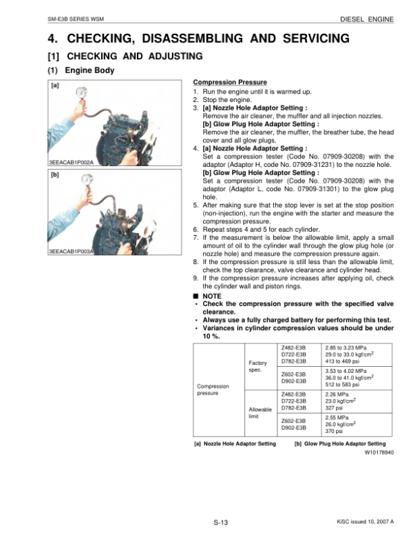
- SM-E3B Series Engine Workshop Service Section
-
04. Hydraulic System — Mechanism, Testing and Repair
- Hydraulic System Construction and Operating Principles
- Main Hydraulic Pump Structure and Function
- Main Control Valve Construction and Operation
- Swivel Motor Structure and Operating Mechanism
- Travel Motor (Wheel Motor) Construction and Operation
- Pilot Valve and Remote Control Valve
- Hydraulic Unload Valve
- Hydraulic Selector Valve
- Hydraulic Component Accessories and Filters
- Auxiliary Service-Port Hydraulic System
- Two Pattern Selection System (TPSS) — PP Version
- Hydraulic Component Layouts — U17-3a and U17/U17-3
- Hydraulic Circuit Diagrams
- Common Hydraulic Circuit Troubleshooting
- Hydraulic Pump and Motor Fault Diagnosis
- Swivel System Performance Troubleshooting
- Travelling System Performance Troubleshooting
- Hydraulic Testing Instruments and Special Tools
- Main Hydraulic Pump Flow Testing
- Hydraulic Pressure Measurement
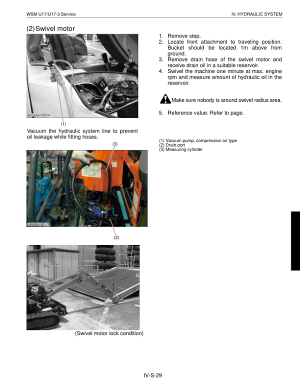
- Hydraulic Motor Drain Flow Measurement
- Hydraulic Motor Block Performance Testing
- Hydraulic Operating Speed Measurement
- Straight-Travel Performance Testing
- Swivel System Diagnosis and Testing
- Travel System Diagnosis and Testing
- Hydraulic Cylinder Natural Fall Measurement
- Control and Travel Lever Operating Force Checks
- Control Lever Stroke Measurement
- Hydraulic Pump Specifications and Relief Valve Settings
- Swivel, Travel and Cylinder Performance Specifications
- Service-Port Flow and Motor Drain Specifications
- Hydraulic Pump Disassembly and Reassembly
- Main Control Valve Disassembly and Reassembly
- Pilot Valve Disassembly and Reassembly
- Swivel Motor Disassembly and Reassembly
- Rotary Joint (Swivel Joint) Servicing
- Travel Motor Disassembly and Reassembly
- Hydraulic Cylinder Disassembly and Reassembly
- Dozer and Track Change Valve Servicing
- Unload Valve and Hydraulic Accumulator Servicing
- Hydraulic Oil Tank and Third-Line Components
- TPSS Valve Servicing — PP Version Only
- Hydraulic Hose Removal and Installation
-
05. Electrical System — KICS and Diagnostics
- Electrical System Features and Control Functions
- Kubota Intelligent Control System (KICS)
- KICS Digital Meter Features
- Electronic Operating Modes and Display Functions
- KICS Service Mode Menus and Functions
- Auto Idling (AI) Control System
- Main Electrical Component Functions
- Electrical Failure Diagnosis
- Service Mode Flowcharts
- Electrical Component Locations
- Electrical Circuit Diagrams — European Version
- Electrical Circuit Diagrams — PP Version
- Wiring Diagrams — European and PP Versions
- General Electrical System Troubleshooting
- Engine Electrical Fault Diagnosis
- Meter Panel and Engine Starting Troubleshooting
- KICS Trouble and Alarm Displays
- Quick Diagnosis and KICS Message Identification
- Electrical Coupler and Connector Inspection
- Electrical Component and Fuse Testing
- Wiring Harness and Battery Inspection
- Electrical Measuring Instruments and Special Tools
- Wiring Harness Installation and Clamping Precautions
- Engine Room and Engine-Top Harness Routing
- Unload Switch and Horn Wiring
- Front Electrical Cable Installation
- High-Speed Travel Switch and Horn Circuits
- Fuel Sensor Wiring and Electrical Connections
- Right-Hand Console Dual-Speed Wiring Harness
- Fuse, Battery and Horn Checking
- Glow Relay and Glow Plug Testing
- Unload Safety Switch Inspection
- High/Low Travel Switch Testing
- Solenoid Valve and Fuel Pump Testing
- Fuel Sensor and Engine Stop Solenoid Inspection
- Coil Commander Servicing
- Coolant Temperature Gauge and Engine Oil Switch Checks
- Electrical Relay Inspection
- Canopy Light Installation — KTA Version
- 06. Conversion Tables
Hydraulic Testing, KICS Diagnostics and Model-Specific Service References
The hydraulic documentation separates component operation from troubleshooting, testing and disassembly. Technical procedures include pump flow and hydraulic pressure measurement, swivel and travel motor drain testing, cylinder natural fall measurements, straight-travel performance checks and control lever adjustment. The PP configuration also includes Two Pattern Selection System (TPSS) references, while regional maintenance information identifies additional hydraulic oil checks for machines equipped with hydraulic breakers.
The Electrical System chapter documents KICS operating and service modes, electronic alarm messages, Auto Idling functions and component-level fault diagnosis. Separate European and PP wiring references help identify the correct circuits, while the U17-3a comparison material distinguishes revised machine arrangements from earlier U17/U17-3 configurations. Engine servicing includes air-cleaner, radiator, fuel-hose and other accessory references, so component inspections should follow the procedures and specifications applicable to the identified machine.


























Reviews
There are no reviews yet.