Overview
The Kubota K008-3 and U10-3 Excavator Workshop Service Manual provides technical documentation for maintenance, troubleshooting, inspection and component repair of these Kubota mini excavators. The workshop reference covers machine identification, front attachments, retractable undercarriage components, engine servicing, hydraulic pumps, control valves, pilot systems, swivel and travel motors, and electrical equipment. Its mechanism and servicing sections provide component specifications, operating principles, diagnostic testing, disassembly, reassembly and repair information.
The documentation includes regional machine specifications, hydraulic breaker maintenance, crawler tension adjustment, retractable track-frame servicing, hydraulic pump flow testing and travel motor performance measurements. Model-specific hydraulic references distinguish main and pilot pump arrangements, control-valve configurations and hydraulic operating circuits. Electrical coverage includes wiring harness installation, engine starting and stopping diagnostics, charging-system checks, sensor inspection and working-light circuits. General information also provides servicing precautions, tightening specifications and post-reassembly inspection requirements.
Notice: The workshop documentation distinguishes EU, KTC, KCL and KTA configurations. Hydraulic control valves, operating arrangements and travel motor specifications may differ between applicable versions. Confirm the machine identification and regional specification before selecting hydraulic circuits, service measurements or component repair procedures.
Table of Contents
Kubota K008-3, U10-3 Manual
- 01. General
- Machine Body and Engine Identification Marks
- Safety Precautions Before Starting Service Work
- Workshop Clothing and Protective Equipment
- Inspection of Workshop Equipment and Tools
- Workshop Organisation and Safety
- Safety Measures During Component Servicing
- Teamwork and Lifting Equipment Precautions
- Preparation for Disassembly
- Cleaning and Initial Equipment Inspection
- Disassembly and Reassembly Precautions
- Essential Adhesives and Critical Functional Processes
- Important Safety-Related Servicing Procedures
- Post-Reassembly Inspection Requirements
- Inspection for Abnormal Noise and Vibration
- Safety Decal and Wiring Harness Clamp Inspection
- Hydraulic Oil Level Checking After Reassembly
- General Servicing Fundamentals
- O-Ring, Oil Seal, Circlip and Roll Pin Servicing
- Hydraulic Piping and Hose Precautions
- Hydraulic Hose and Joint Specifications
- Hydraulic Hose Clamp Tightening Torques
- Hydraulic Pipe Nut and Elbow Specifications
- General Bolt and Nut Tightening Torques
- Machine Quality Specifications — EU Version
- Machine Quality Specifications — KTC, KCL and KTA Versions
- Scheduled Maintenance Intervals
- Hydraulic Oil Checks for Machines with Hydraulic Breakers
- 02. Machine Body — Mechanism and Servicing
- Machine Specifications — EU Version
- Machine Specifications — KTC, KCL and KTA Versions
- Bucket Component Interchangeability
- Machine Body Structure and Arrangement
- Operating Lever Lock Mechanism — K008-3
- Travel Operating Lever Linkage
- Main Operating Lever Construction
- Dozer Control Linkage — K008-3
- Swing and Service Port Controls — K008-3
- Accelerator Lever Mechanism
- Retractable Track Frame Change Lever
- Engine Mounting Components
- Undercarriage Construction
- Crawler Tension Mechanism
- Track Roller Arrangement
- Retractable Undercarriage Mechanism
- Rubber Crawler Construction
- Machine Weight and Service Specifications
- Operating Lever Stroke and Operating Force
- Front Attachment Pin Dimensions
- Bucket and Rubber Crawler Dimensions
- Track Roller, Idler and Sprocket Specifications
- Dozer Blade Dimensions
- Component Weight References
- Water and Oil Quantity References
- Front Attachment Assembly Procedures
- Front Attachment Greasing Points
- Mechanical Operating Unit Servicing
- Accelerator Lever Disassembly and Assembly
- Dozer Operating Lever Servicing
- Boom Swing Pedal Servicing
- Auxiliary Service Port Pedal Servicing
- Hydraulic Oil Tank Servicing
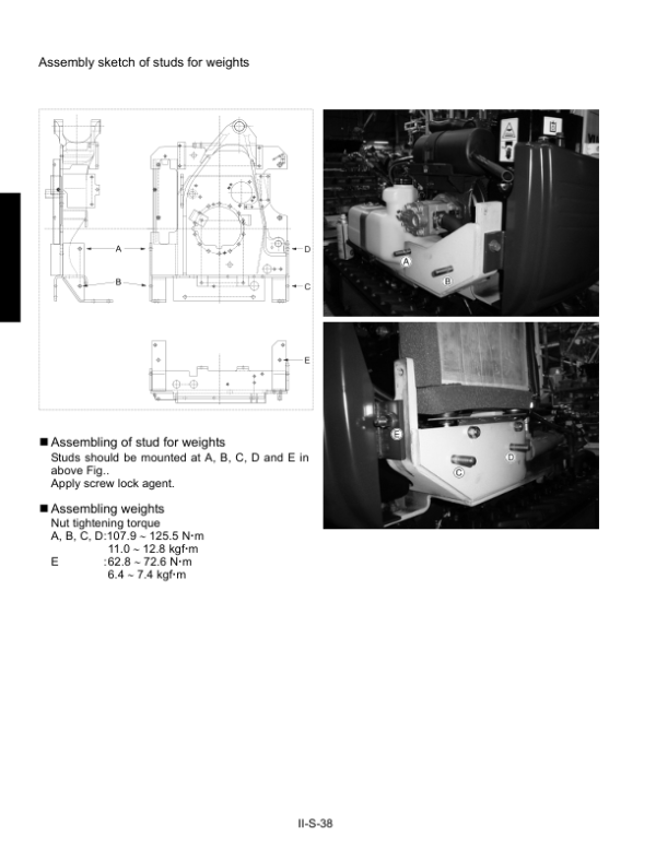
- Machine Counterweight Servicing
- Swivel Bearing Assembly — K008-3
- Swivel Bearing Assembly — U10-3
- ROPS Structure and Servicing
- Operator Seat Belt Installation Angle
- Front Idler and Track Take-Up Assembly
- Track Roller Inspection and Assembly
- Track Tension Grease Cylinder
- Adjustable Track Frame Assembly
- Adjustable Track Hose Routing
- Crawler Adjustment Procedures
- 03. Engine — Mechanism and Servicing
- Engine Safety Information
- Engine Technical Specifications
- Engine Electrical Components
- Engine Performance Curves
- Engine Dimensions
- Engine Mounting Arrangement
- Engine Brackets and Vibration-Resistant Mounts
- Engine Muffler Components
- Engine Identification
- General Engine Servicing Precautions
- Special Fastener Tightening Torques
- General Engine Fastener Tightening Torques
- Main Bearing Case Assembly — Type 1
- Main Bearing Case Assembly — Type 2
- 04. Hydraulic System — Mechanism and Servicing
- Main Hydraulic Pump — K008-3 and U10-3
- Pilot Hydraulic Pump — U10-3
- Main Hydraulic Control Valve Specifications
- Hydraulic Control Valve Construction
- Control Valve Sectional Arrangement — K008-3 EU Version
- Control Valve Sectional Arrangement — K008-3 KTC, KCL and KTA Versions
- Control Valve Sectional Arrangement — U10-3
- Control Valve Relief Valve Operation
- Anti-Cavitation Valve Function
- Load Check Valve Function
- Pilot Control Valve Construction
- Pilot Valve Control Diagram
- Pilot Valve Operating Principles
- Hydraulic Pilot Circuit
- Pilot Oil Flow with Control Lever Locked
- Pilot Oil Flow with Control Lever Unlocked
- Hydraulic Oil Flow During Boom Lifting
- Hydraulic Oil Flow During Bucket Dumping
- Hydraulic Oil Flow During Arm Crowding
- Hydraulic Oil Flow During Right Swivel Operation
- Swivel Motor Construction and Specifications
- Swivel Motor Operating Principles
- Hydraulic Rotary Joint
- Single-Speed Travel Motor — K008 EU Version
- Two-Speed Travel Motor Construction and Specifications
- Hydraulic Circuit — K008-3 EU Version
- Hydraulic Circuit — K008-3 KTC, KCL and KTA Versions
- Hydraulic Circuit — U10-3 EU Version
- Hydraulic Component Layout
- General Hydraulic System Troubleshooting
- Swivel System Troubleshooting
- Travel System Troubleshooting
- Hydraulic Pump Discharge Specifications
- Hydraulic Pressure Specifications
- Relief Valve Pressure References
- Hydraulic System Noise Specifications
- Swivel and Travel Performance Specifications
- Hydraulic Cylinder Speed Specifications
- Hydraulic Cylinder Natural Fall Specifications
- Boom, Arm, Bucket, Swing and Blade Cylinder Specifications
- Hydraulic Pump Flow Testing
- Pilot Primary Pressure Testing — U10-3
- Pilot Secondary Pressure Testing — U10-3
- Main Relief Valve Pressure Testing
- Swivel Motor Block Performance Testing
- Travel Motor Block Performance Testing
- Boom Cylinder Operating Speed Measurement
- Arm Cylinder Operating Speed Measurement
- Bucket Cylinder Operating Speed Measurement
- Swing Cylinder Operating Speed Measurement
- Dozer Blade Cylinder Operating Speed Measurement
- Swivel Speed Measurement
- Travel Speed Measurement
- Straight Travel Performance Testing
- Hydraulic Cylinder Natural Fall Measurement
- Operating Lever Force and Stroke Measurement
- Hydraulic Pump Coupling Disassembly
- Main Hydraulic Pump Disassembly and Assembly
- Hydraulic Pump Delivery Hose Routing
- Pilot Pump Assembly — U10-3
- Main Control Valve Disassembly and Assembly
- Hydraulic Control Valve Joint Servicing
- Pilot Valve and Hydraulic Operating Unit
- Hydraulic Operating Unit Components — U10-3
- Hydraulic Unload Valve Servicing
- Super Change Valve Servicing
- Hydraulic Relief Valve Assembly
- Pilot Valve Disassembly and Assembly
- Hydraulic Operating Unit Air Bleeding — U10-3
- Swivel Motor Mounting Position — K008-3
- Swivel Motor Mounting Position — U10-3
- Swivel Motor Disassembly and Assembly
- Swivel Joint Disassembly and Assembly
- Travel Motor Adaptor Installation
- Travel Motor Hydraulic Hose Routing
- Travel Motor Disassembly and Assembly
- Travel Motor Troubleshooting
- Hydraulic Cylinder Disassembly and Assembly
- Hydraulic Cylinder Inspection
- Control Valve Hydraulic Hose Routing
- Fixed-Leg Single-Speed Hydraulic Hose Arrangement
- Hydraulic Return Hose Routing
- 05. Electrical System — Inspection and Servicing
- Electrical Wiring Harness Arrangement
- Electrical Wiring Harness Sections
- Electrical Cable and Harness Clamping Precautions
- Control Valve Wiring Connections
- Fuel Sensor Wiring
- Battery Positive and Negative Cable Routing
- Alternator Wiring Harness
- Engine Oil Pressure Switch Wiring
- Slow-Blow Fuse Wiring
- Engine Breather Wiring Clamps
- Radiator Support Wiring Routing
- Swivel Frame Wiring Harness
- Body Ground and Battery Negative Connections
- Working Light Electrical Wiring
- Electrical System Troubleshooting Procedures
- Electrical Connector Voltage and Continuity Testing
- Electrical Connector Pin Removal
- Fuse Inspection
- Electrical Wiring Harness Testing
- Battery Handling and Inspection
- Electrical Measuring Instruments and Special Tools
- Engine Electrical Troubleshooting
- Instrument Panel Diagnosis with Key Switch ON
- Instrument Panel Diagnosis During Engine Starting
- Starter Motor Inspection
- Engine Stop System Inspection
- Charging System Testing
- Horn, Fuel Pump and Working Light Inspection
- Charging Warning Lamp Inspection
- Engine Oil Warning Lamp Inspection
- Fuel Warning Lamp Inspection
Pilot Hydraulic Control Differences and Post-Reassembly Verification
The hydraulic documentation distinguishes the main pump arrangement from the pilot pump and hydraulic operating unit used on the U10-3. Dedicated servicing information includes pilot pressure testing, hydraulic operating unit components and air-bleeding procedures. The K008-3 documentation also separates European and KTC/KCL/KTA control-valve configurations. These differences are important when identifying valve assemblies, interpreting hydraulic pressure measurements or selecting the appropriate circuit diagram for troubleshooting.
The workshop reference also identifies retractable undercarriage components, adjustable track-frame hose routing and crawler adjustment procedures. Following disassembly and reassembly, the General section specifies inspections for abnormal noise and vibration, safety decal and wiring clamp positions, and hydraulic oil level under the stated machine posture. These checks provide a documented basis for confirming assembly condition before returning the excavator to service.




























Reviews
There are no reviews yet.