Overview
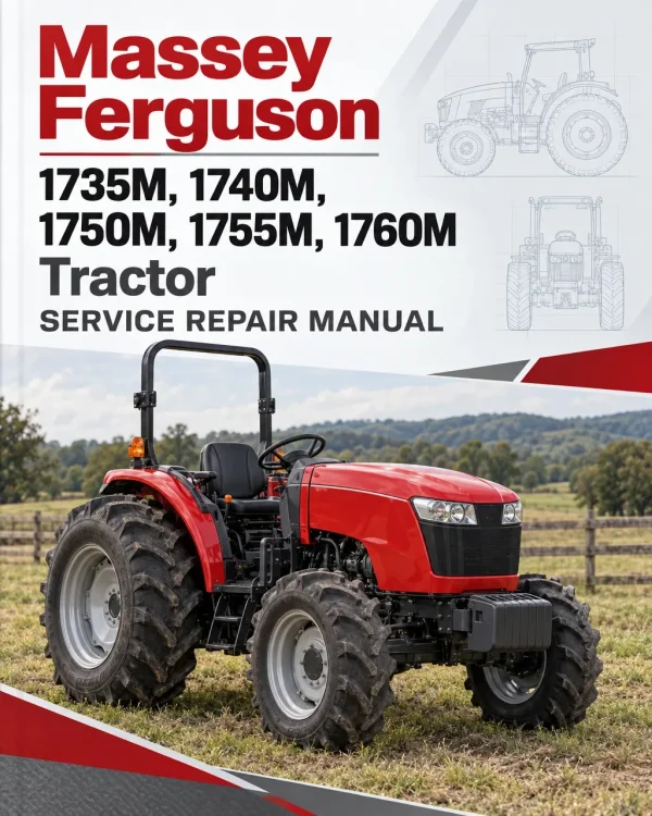
The Massey Ferguson 1735M, 1740M, 1750M, 1755M and 1760M Tractor Workshop Service Manual provides technical information for maintaining, troubleshooting and repairing these Massey Ferguson 1700M Series compact tractors. It includes model specifications, component identification, maintenance procedures, service adjustments, electrical diagnostics and system reference diagrams for workshop use.
Coverage includes engine, fuel and exhaust systems, Power Shuttle and hydrostatic drivetrain configurations, chassis, cab, air conditioning and heating, front and rear axles, brakes, steering and hydraulics. The electrical documentation provides additional information on electronic controllers, sensors, switches, fault codes, instrument panel programming and transmission-related calibrations.
The manual also includes model-specific electrical wiring and hydraulic circuit diagrams, with separate references for MF 1735M, 1740M, 1750M, 1755M and 1760M tractor configurations. These references help technicians identify the appropriate electrical connections, component locations and diagnostic procedures during inspection or repair.
Safety: The General chapter contains operating and workshop safety precautions covering rollover protection, PTO equipment, high-pressure hydraulic leaks, fuel systems, batteries, engine servicing and other maintenance activities. Review the applicable safety information before carrying out inspection, disassembly or repair work.
Notice: The documentation covers both Power Shuttle and hydrostatic transmission configurations, as well as cab and platform tractor arrangements. Select the specifications, electrical diagrams and service procedures applicable to the tractor’s model and installed equipment.
Table of Contents
Massey Ferguson 1735M, 1740M, 1750M, 1755M, 1760M Manual
-
1. General
- 1.1 General Information
- 1.2 Safety
- 1.3 Machine Identification
- 1.4 Specifications
- 1.5 Lubrication and Maintenance
- 1.6 Machine Main Components
- 1.7 General Precautions for Repair
-
2. Engine, Fuel and Exhaust System
- 2.1 Component Access
- 2.2 Radiator
- 2.3 Fuel Tank
- 2.4 Remove or Install the Engine
- 2.5 Engine Service Manual
- 3. Drive Train System
- 4. Chassis
- 5. Cab
- 6. Air Conditioning and Heating System
- 7. Axles
- 8. Brake System
- 9. Steering System
- 10. Hydraulic System
-
11. Electrical System
- 11.1 Basic Troubleshooting Information
- 11.2 Calibrations
- 11.3 Instrument Panel
- 11.4 Instrument Panel Setup, Programming and Checks
- 11.5 Controllers
- 11.6 Solenoids
- 11.7 Sensors and Switches
- 11.8 Fuses and Relays
- 11.9 Electrical and Hydraulic Control System
- 11.10 Main Clutch System
- 11.11 Hydrostatic Transmission
- 11.12 Electronic Diagnostic Tool
- 11.13 Fault Code Display
- 11.14 Vehicle Fault Codes
- 11.15 Engine Fault Codes
- 11.16 Connectors
-
12. Diagrams
- 12.1 Wiring Diagrams
- 12.2 Hydraulic Diagrams
Power Shuttle and Hydrostatic Transmission Diagnostics
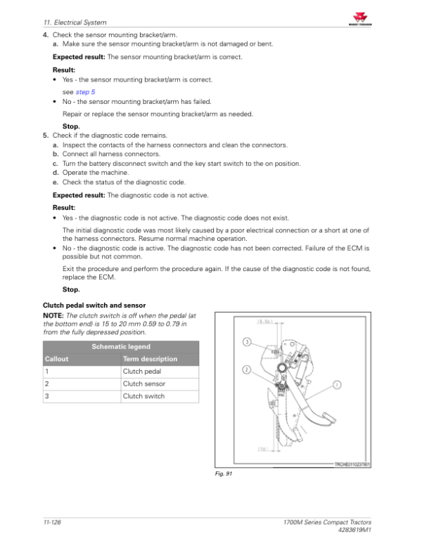
The service documentation distinguishes Power Shuttle and hydrostatic transmission configurations, including their individual specifications and electronic controls. The electrical chapter contains procedures for calibrating accelerator sensors, clutch pedal switches, hydrostatic transmission pedal sensors and hydrostatic transmission performance.
Additional references cover Power Shuttle solenoids, main clutch control, PTO solenoids, forward and reverse switches, hydrostatic response controls, cruise control, engine stall control and oil temperature control. These sections support troubleshooting when drivetrain operation or electronic control performance requires inspection.
Electrical Fault Codes and Component Testing
The electrical documentation includes continuity testing, voltage checks, open-circuit diagnosis, short-circuit testing and high-resistance fault detection. Further sections cover the engine control unit, vehicle control unit, instrument panel, electrical switches, solenoids, fuses, relays and connector identification.
Dedicated diagnostic references include vehicle and engine fault codes with SPN, FMI and engine diagnostic code identifiers. The instrument panel chapter also provides procedures for checking sensors, programming engine and model settings, configuring tire size and speed units, and reviewing stored fault information.
Model-Specific Wiring and Hydraulic Circuit Diagrams
The wiring diagram chapter provides separate engine electrical diagrams for the MF 1735M and 1740M, and for the MF 1750M, 1755M and 1760M. It also distinguishes Power Shuttle wiring harnesses for the MF 1760M from those used on the other listed models, alongside hydrostatic transmission wiring, sensor connections, solenoid circuits and cab electrical references.
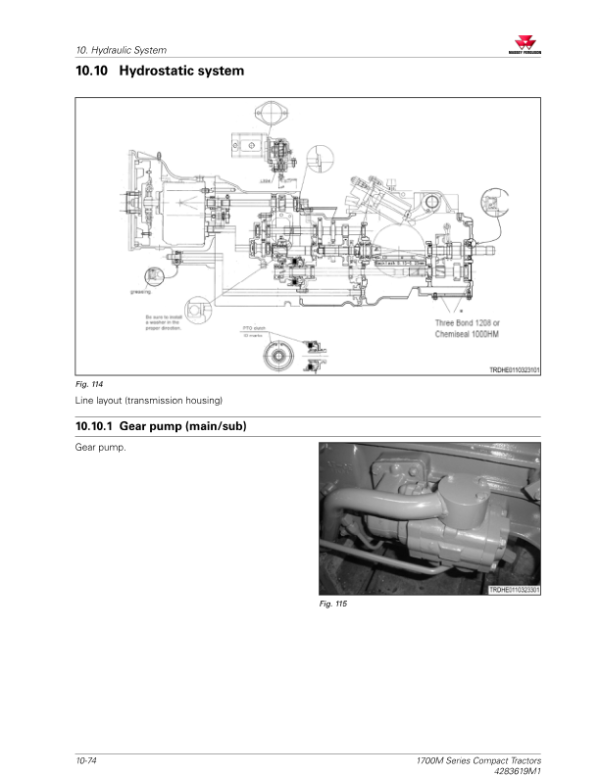
The hydraulic diagrams are similarly organised by tractor and drivetrain configuration, including Power Shuttle hydraulic circuits for the MF 1735M and 1740M, MF 1750M and 1755M, and MF 1760M, plus a separate hydrostatic tractor hydraulic diagram. Refer to the applicable circuit information when tracing hydraulic or electrical faults.
Service Specifications and Maintenance References
The General chapter provides machine identification information, engine and transmission specifications, hydraulic capacities, lubrication requirements, axle and brake specifications, wheel bolt tightening torques and tire inflation pressures. It also contains maintenance charts, lubrication fill and drain locations, and general precautions for component removal and installation.
Engine-related service information includes radiator and fuel tank access, fuel filter replacement, fuel system air removal, and engine removal and installation. Consult the relevant component identification information and model specifications before undertaking maintenance or repair procedures.




















Reviews
There are no reviews yet.