Overview
The Massey Ferguson 2210, 2225 and 2235 Tractor Workshop Service Repair Manual provides detailed technical information for maintaining, inspecting, troubleshooting and repairing these Massey Ferguson agricultural tractors. The workshop documentation covers diesel engine servicing, clutch assemblies, mechanical transmissions, hydraulic Hi-Lo components, rear axle and differential systems, power take-off equipment, two-wheel-drive and four-wheel-drive front axles, hydraulic circuits, electronic power lift controls, electrical equipment and operator cab systems.
Technical coverage includes engine timing procedures for the 903.27, 1004.40 and 1004.42 engines, gearbox removal and overhaul, rear differential and final drive servicing, hydraulic and mechanical PTO mechanisms, front axle repairs, brake adjustments and hydraulic pressure testing. Additional sections address tractor separation procedures, DNX front axles, bevel-gear front axle assemblies, Spring-on and hydraulic four-wheel-drive engagement systems, mechanical and electronic lift controls, steering hydraulics, electrical wiring diagrams, air-conditioning equipment, workshop specifications and special service tools.
Important Information: The workshop documentation contains separate rear final drive references for the MF 2210 and MF 2225/2235 tractors. It also covers multiple front axle arrangements, engine timing references and hydraulic system configurations. Identify the tractor model, engine, axle type and installed hydraulic equipment before selecting the applicable service procedure.
Table of Contents
Massey Ferguson 2210, 2225, 2235 Manual
-
01. Introduction, Specifications and Workshop Safety
- Introduction to the Workshop Manual
- Workshop Manual Structure and Technical References
- Tractor Identification
- Tractor Weights and Dimensions
- Diesel Engine Specifications
- Clutch Technical Specifications
- Transmission Specifications
- Power Take-Off Specifications
- Two-Wheel-Drive Front Axle Specifications
- DNX Four-Wheel-Drive Front Axle Specifications
- Four-Wheel-Drive Bevel Gear Axle Specifications
- Hydraulic Circuit Specifications
- General Workshop Safety
- Accident Prevention Procedures
- Tractor Safety and Danger Decals
- Safe Replacement of Tractor Components
- Safe Tractor Operation
- Pre-Delivery Inspection Procedures
- Routine Tractor Maintenance Guide
- Technical Measurement Conversion Tables
- Length, Area and Volume Conversions
- Weight and Pressure Conversions
- Torque and Temperature Conversions
- Workshop Sealants
- Bolt Tightening Torque Tables
- General Mechanical Assembly Instructions
- Oil Seal Installation
- O-Ring Seal Installation
- Bearing Installation
-
02. Separation of Tractor Assemblies
- Tractor Splitting Precautions and Safety Recommendations
- Cab Separation from Tractor
- Cab Removal Sequence
- Cab Reassembly and Installation Sequence
- Operator Platform Separation from Tractor
- Platform Removal Procedure
- Platform Reinstallation Procedure
- Engine Separation from Axle Assembly
- Identification of Accessible Main Assemblies
- Engine and Axle Separation Procedure
- Engine and Axle Reassembly Procedure
- Axle Separation from Gearbox
- Axle and Gearbox Splitting Sequence
- Axle and Gearbox Reconnection Procedure
- Gearbox Separation from Differential Housing
- Gearbox and Differential Housing Splitting Sequence
- Gearbox and Differential Housing Reassembly
-
03. Diesel Engine Service and Timing
- Engine Service Precautions
- Engine General Technical Specifications
- Standard Engine Tightening Torques
- Engine 903.27 Tightening Torque Specifications
- Engine 1004.40 and 1004.42 Tightening Torques
- Engine 903.27 Timing Procedures
- Engine 903.27 Timing Introduction
- Number One Cylinder Compression Top Dead Centre Identification
- Camshaft Timing Inspection – Engine 903.27
- Fuel Injection Pump Locking Angle Inspection
- Fuel Injection Pump Timing – Engine 903.27
- Engine 1004.40 Timing Procedures
- Engine 1004.42 Timing Procedures
- Number One Cylinder Compression TDC – 1004.40/1004.42
- Camshaft Timing Inspection – 1004.40/1004.42
- Fuel Injection Pump Timing – 1004.40/1004.42
-
04. Clutch System
- Clutch General Description
- Clutch Assembly and Component Drawings
- Clutch Operating Principles
- Clutch Technical Specifications
- Clutch Removal from Tractor
- Clutch Disassembly
- Clutch Component Inspection
- Clutch Reassembly
- Clutch Adjustment Procedures
- Special Clutch Service Tools
-
05. Gearbox and Transmission System
- Transmission General Description
- Transmission Assembly Drawings
- Gearbox Exploded Component Drawings
- Gear Engagement Forks and Levers
- Rear Transmission Unit
- Transmission Final Drive Arrangement
- Tractor Ground Speed Tables
- Transmission Technical Specifications
- Transmission Power Train Diagram
- Engine and Gearbox Assembly Without Hydraulic Hi-Lo
- Engine-Gearbox Assembly Removal
- Engine-Gearbox Assembly Disassembly
- Engine-Gearbox Component Inspection
- Engine-Gearbox Reassembly
- Engine-Gearbox Special Tools
- Gearbox Main Component Identification
- Gearbox Removal from Tractor
- Gearbox Disassembly
- Gearbox Inspection
- Gearbox Reassembly
- Gearbox Special Service Tools
- Hydraulic Hi-Lo Transmission
- Hydraulic Hi-Lo Assembly Drawings
- Hydraulic Hi-Lo Operating Principles
- Hydraulic Hi-Lo Removal and Disassembly
- Hydraulic Hi-Lo Component Inspection
- Hydraulic Hi-Lo Reassembly
- Hydraulic Hi-Lo Special Service Tools
-
06. Rear Axle, Differential, Final Drives and Brakes
- Rear Differential and Bevel Gear Assembly
- Rear Differential Component Drawings
- Bevel Gear and Differential Removal
- Rear Differential Disassembly
- Rear Differential Inspection
- Bevel Gear and Differential Reassembly
- Rear Differential Special Service Tools
- Rear Final Drive Assemblies
- MF 2210 Rear Final Drive
- MF 2210 Final Drive Component Identification
- MF 2210 Final Drive Removal and Disassembly
- MF 2210 Final Drive Inspection
- MF 2210 Final Drive Reassembly
- MF 2210 Final Drive Special Tools
- MF 2225 and MF 2235 Rear Final Drives
- MF 2225/2235 Final Drive Component Identification
- MF 2225/2235 Final Drive Removal and Disassembly
- MF 2225/2235 Final Drive Inspection
- MF 2225/2235 Final Drive Reassembly
- MF 2225/2235 Final Drive Special Tools
- Rear Brake Operating Principles
- Brake Assembly Disassembly
- Brake Component Inspection
- Rear Brake Reassembly
- Brake Pedal Adjustment
- Handbrake Adjustment
- Brake Hydraulic Circuit Air Bleeding
-
07. Power Take-Off (PTO)
- Power Take-Off General Description
- PTO Assembly and Component Drawings
- PTO Operating Principles and Types
- Two-Speed Hydraulic PTO
- Hydraulic PTO Operating Principles
- Mechanical Power Take-Off
- PTO Technical Specifications
- PTO Unit Access Procedures
- PTO Removal from Tractor
- PTO Assembly Disassembly
- PTO Component Inspection
- PTO Reassembly
- Special PTO Service Tools
-
08. Front Axles and Four-Wheel-Drive Engagement
- Front Axle General Service Precautions
- DNX Four-Wheel-Drive Front Axle
- DNX Standard Front Axle Component Drawings
- DNX Standard Axle Operating Principles
- DNX Sherpa Front Axle Arrangement
- DNX Front Axle Technical Specifications
- DNX Standard Axle Removal
- DNX Standard Axle Disassembly
- DNX Standard Axle Inspection
- DNX Standard Axle Reassembly
- DNX Sherpa Final Drive Disassembly
- DNX Sherpa Final Drive Inspection
- DNX Sherpa Final Drive Reassembly
- DNX Front Axle Special Service Tools
- Four-Wheel-Drive Front Axle with Bevel Gear Pairs
- Bevel Gear Axle Component Drawings
- Bevel Gear Axle Operating Principles
- Bevel Gear Front Axle Technical Specifications
- Bevel Gear Front Axle Removal
- Bevel Gear Front Axle Disassembly
- Bevel Gear Front Axle Inspection
- Bevel Gear Front Axle Reassembly
- Special Tools for Bevel Gear Front Axle
- Two-Wheel-Drive Front Axle
- 2WD Front Axle Component Drawings
- 2WD Front Axle Technical Specifications
- 2WD Front Axle Removal
- 2WD Front Axle Disassembly
- 2WD Front Axle Inspection
- 2WD Front Axle Reassembly
- 2WD Front Axle Special Tools
- Four-Wheel-Drive Engagement System
- Hydraulic 4WD Engagement Clutch
- Hydraulic Clutch Operating Principles
- Spring-On Four-Wheel-Drive Engagement Unit
- Spring-On Unit Operating Principles
- 4WD Engagement System Technical Specifications
- Hydraulic 4WD Clutch Removal and Disassembly
- Hydraulic Engagement Clutch Inspection
- Hydraulic 4WD Clutch Reassembly
- Spring-On Unit Removal and Disassembly
- Spring-On Unit Inspection
- Spring-On Unit Reassembly
- 4WD Engagement Special Service Tools
-
09. Hydraulic Circuit, Power Steering and Mechanical Lift
- Hydraulic System Safety Precautions
- Hydraulic System General Description
- Hydraulic Circuit Overview
- Low-Pressure Hydraulic Circuit
- High-Pressure Hydraulic Circuit
- Hydraulic Cooling and Lubricating Circuit
- Hydraulic System Technical Specifications
- Low-Pressure Hydraulic Pump
- Hydraulic Pump Operating Principles
- Hydraulic Pump Disassembly
- Hydraulic Pump Inspection
- Hydraulic Pump Reassembly and Adjustment
- Hydraulic Pump Special Tools
- Hydraulic Filter Operation and Maintenance
- Hydraulic Power Steering System
- Power Steering Hydraulic Circuit
- Power Steering Assembly Drawings
- Power Steering Operating Principles
- Power Steering Unit Removal
- Power Steering Unit Disassembly
- Power Steering Inspection
- Power Steering Reassembly and Adjustment
- Power Steering Special Tools
- Hydraulic Power Pack Assemblies
- Comatrol Hydraulic Power Pack
- Comatrol Power Pack Operating Principles
- Comatrol Power Pack Component Servicing
- 18-Bar Calibration Valve
- 15-Bar Calibration Valve
- Hydraulic Compensating Valve
- Hydraulic Pressure Detection Component
- Hydraulic Solenoid Valve
- Oleodinamica Slanzi Hydraulic Power Pack
- Oleodinamica Slanzi Power Pack Operating Principles
- Oleodinamica Slanzi Power Pack Removal
- 18-Bar Valve Inspection and Calibration
- 5-Bar Valve Inspection and Calibration
- PTO Clutch Modulating Governor Valve
- Front and Rear Differential Lock Hydraulic Supply
- PTO and PTO Brake Hydraulic Supply
- Four-Wheel-Drive and Fast Run Hydraulic Supply
- Spring-On Hydraulic Fluid Supply
- Hydraulic Hi-Lo Fluid Supply
- High-Pressure Hydraulic Circuit Components
- Trailer Brake Control Valve
- Trailer Brake Valve for Italian Configuration
- Trailer Brake Valve for Export Configuration
- Trailer Brake Operating Phases
- Trailer Brake Valve Pressure Inspection and Adjustment
- Auxiliary Hydraulic Control Valves
- Auxiliary Valve Inlet Unit
- Standard Single/Double-Acting Control Valve
- Floating Hydraulic Control Valve
- Automatic-Release Control Valve
- Control Valve for Hydraulic Motors
- Mechanical Hydraulic Power Lift
- Mechanical Power Lift Component Drawings
- Power Lift Position Control
- Power Lift Draft Control
- Mixed Position and Draft Control
- Power Lift Floating Mode
- Mechanical Lift Control Valve Assembly
- Lift Control Valve Neutral Position
- Lift Control Valve Delivery Position
- Lift Control Valve Discharge Position
- Mechanical Power Lift Removal
- Mechanical Lift Disassembly and Inspection
- Mechanical Lift Preliminary Adjustment
- Mechanical Lift Reassembly and Installation
- Lift Control Valve System Removal
- Lift Control Valve Disassembly and Inspection
- Lift Control Valve Hydraulic Adjustment
- Anti-Shock Valve Inspection and Adjustment
- Hydraulic Discharge Valve Leak Inspection
- Hydraulic Check Valve Leak Inspection
- Maximum Pressure Valve Calibration
- Hydraulic Delivery Duct Leak Inspection
- Mechanical Lift Sensitivity Adjustment
- Position Control Adjustment
- Draft Control Adjustment
- Mechanical Power Lift Troubleshooting
- Mechanical Power Lift Special Tools
- Hydraulic Operating Pressure Testing
- Low-Pressure Circuit Pressure Checks
- High-Pressure Circuit Pressure Checks
- Hydraulic Pressure Testing Special Tools
-
10. Electrical System and Wiring Diagrams
- Electrical System Safety Precautions
- Electrical System General Description
- Electrical System Technical Specifications
- Main Tractor Wiring Diagram
- Operator Cab Wiring Diagram
- Control Panel Wiring Diagram
- Electrical Sensor Locations
- Electrical Fuse Protection
- Electrical Fuse Boxes
- Electrical Relays
-
11. Electronic Power Lift and Control System
- Electronic Power Lift Safety Precautions
- Electronic Power Lift General Description
- Electronic Lift Main Components
- Electronic Power Lift Technical Specifications
- Electronic Power Lift Hydraulic Circuit
- Electronic Lift Hydraulic Operating Principles
- Electronic Lift Valve Block
- Electronic Lift Control Valve System
- Electronic Lift Control Valve Components
- Electronic Lift Neutral Position
- Electronic Lift Lowering Position
- Electronic Lift Raising Position
- Electronic Lift Electrical System
- Electronic Power Lift Wiring Diagram
- Electronic Wiring and Connector Types
- Electronic Connector Locations
- Electronic Lift Control Console
- Electronic Control Components
- External Electronic Lift Buttons
- Electronic Lift Sensors
- Electronic Lift Shock Absorber Function
- Electronic Lift Functional Tests
- Electronic Lift Quick Operating Test
- Electronic Power Lift Troubleshooting
- Electronic Fault Identification
- Electronic Lift Test Instruments
- Electronic Lift Fault Code Tables
- Electronic Lift Terminal and Connector Identification
- Electronic Lift Hydraulic Pressure Tests
- Electronic Power Lift Special Service Tools
-
12. Operator Cab and Equipment
- Cab Service Safety Precautions
- Operator Cab General Description
- Operator Cab General Layout
- Operator Cab Main Controls
- Cab Technical Specifications
- Cab Air Conditioning System
- Air Conditioning Operating Principles
- Air Conditioning Main Components
- Air Conditioning Safety Instructions
- Air Conditioning System Maintenance
- Cab Air Conditioning Wiring Diagram
- Cab and Air Conditioning Special Service Tools
-
13. Auxiliary Equipment and Hydraulic Accessories
- Auxiliary Hydraulic Control Valve Arrangements
- Standard Single/Double-Acting Auxiliary Control
- Floating Hydraulic Control Functions
- Automatic-Release Auxiliary Control Valve
- Hydraulic Motor Control Valve
- Trailer Brake Hydraulic Control – Italian Configuration
- Trailer Brake Hydraulic Control – Export Configuration
- Hydraulic PTO and PTO Brake Supply
- Four-Wheel-Drive Engagement Hydraulic Equipment
- Hydraulic Hi-Lo Control Equipment
- Cab Air Conditioning Equipment
-
14. Special Workshop Service Tools
- Clutch Special Service Tools
- Engine-Gearbox Assembly Special Tools
- Transmission and Gearbox Special Tools
- Rear Differential Special Tools
- MF 2210 Rear Final Drive Special Tools
- MF 2225/2235 Rear Final Drive Special Tools
- Hydraulic Hi-Lo Special Tools
- DNX Front Axle Special Tools
- Four-Wheel-Drive Bevel Gear Axle Special Tools
- Two-Wheel-Drive Front Axle Special Tools
- Four-Wheel-Drive Engagement Special Tools
- Power Take-Off Special Tools
- Hydraulic Pump Service Tools
- Power Steering Service Tools
- Trailer Brake Control Valve Service Tools
- Mechanical Power Lift Service Tools
- Hydraulic Pressure Testing Tools
- Electronic Power Lift Test Instruments and Tools
- Cab and Air Conditioning Service Tools
Rear Final Drive, Front Axle and Hydraulic Lift Identification
The Massey Ferguson 2210, 2225 and 2235 workshop manual includes different servicing references for selected drivetrain components. The rear final drive documentation specifically separates the MF 2210 assembly from the assemblies used on MF 2225 and MF 2235 tractors. Each reference includes component drawings and removal, disassembly, inspection and reassembly procedures, together with applicable special tools.
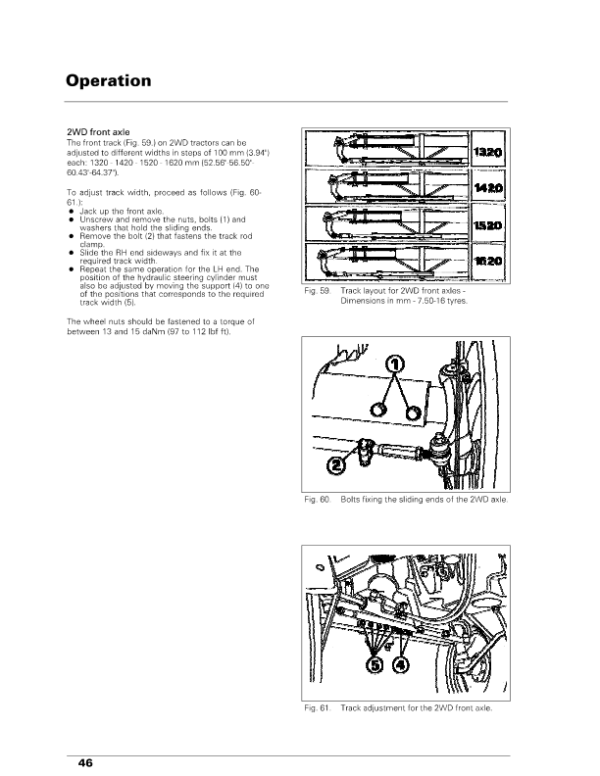
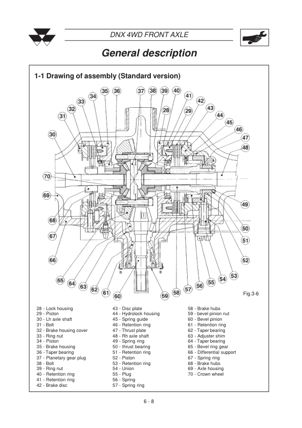
The front axle documentation also distinguishes DNX four-wheel-drive axles in standard and Sherpa versions, four-wheel-drive axles with bevel gear pairs, and two-wheel-drive axle arrangements. Separate procedures cover hydraulic and Spring-on four-wheel-drive engagement systems. Use the section matching the installed axle design and engagement mechanism when carrying out front drivetrain repairs.
Hydraulic lift servicing is divided between mechanical power lift controls and electronic power lift equipment. The mechanical system includes position, draft, mixed and floating control references, while the electronic system has dedicated wiring diagrams, sensors, control components, functional tests, fault code tables and hydraulic pressure checks. Confirm the installed lift control system before using the corresponding adjustment, testing or troubleshooting procedures.




















Reviews
There are no reviews yet.