Dyna-VT Transmission Maintenance and Diagnostic Procedures
The gearbox documentation covers ML130 and ML160 continuously variable transmission systems, including Dyna-VT operating principles, Dyna-TM traction control references, electronic error codes and electrical and hydraulic circuit diagrams. The diagnostic sections include hydrostatic loop inspection, hydraulic pressure measurement, safety-function testing and gearbox electrical testing.
Further procedures describe controller programming, parameter settings, forward speed calibration, throttle pedal potentiometer adjustment, armrest lever calibration and Autotronic 4 functions. The repair sections include disassembly and reassembly of the Dyna-VT unit, transmission filling, forward/reverse high-pressure relief valves and flushing valve servicing.
Rear Axle, Differential and Braking System Servicing
The HA130/160 rear axle documentation includes final drive assemblies, differential components, electrical control diagrams and mechanical repair procedures. Detailed topics cover removal and refitting of final drive units, differential and pinion disassembly, electronic diagnostic tests, programming and system calibration.
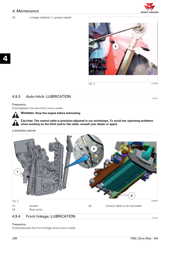
Tractor braking references include hydraulic brake components, wheel brake cylinders, brake bleeding and ParkLock. Separate sections cover hydraulic trailer braking, pneumatic trailer braking and the Auto-Hitch system. The pneumatic trailer braking material distinguishes German, English and Italian system arrangements, allowing the appropriate component and testing references to be selected.
Dana Suspended Front Axles and Four-Wheel-Drive System
The front axle documentation provides dedicated technical sections for Dana 735, 740, 745, 750 and 755 axle arrangements. Each axle group includes electrical and hydraulic diagrams, fault codes, diagnostic testing, programming, calibration and disassembly or reassembly references. Additional documentation addresses the four-wheel-drive clutch, including electrical controls, system testing and adjustment procedures.
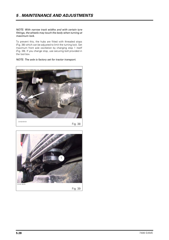
Identify the axle fitted to the tractor before carrying out suspended front axle calibration, electrical diagnosis or component removal. The applicable axle and control system procedures should be used when inspecting the suspension or four-wheel-drive equipment.
Electronic Control Systems, Datatronic 3 and Auto-Guide
The electronics chapter provides technical information for the DCC2 instrument display, Datatronic 3, ISOBUS and Auto-Guide systems. It includes controller electrical connections, CAN network diagrams, instrument panel error codes, system parameter settings and programming instructions.
Auto-Guide references include diagnostic testing, steering unit valve programming, TopDock configuration, authorisation code procedures, radio parameter settings, DMU calibration and Auto-Guide harness installation. Additional diagrams distinguish Datatronic 3 and non-Datatronic 3 tractor configurations, as well as joystick and FingerTIP control arrangements.
Model Identification and Workshop Specifications
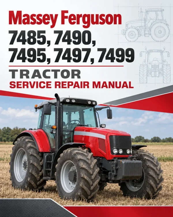
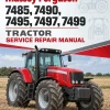
The introductory documentation includes tractor specifications for the Massey Ferguson 7485, 7490, 7495, 7497 and 7499, along with dimensions, weights, attachment points and capacities. It also includes additional 7400 Series model information, conversion tables, retaining compounds, sealing products, electrical diagrams, hydraulic diagrams, fault codes and calibration procedures.
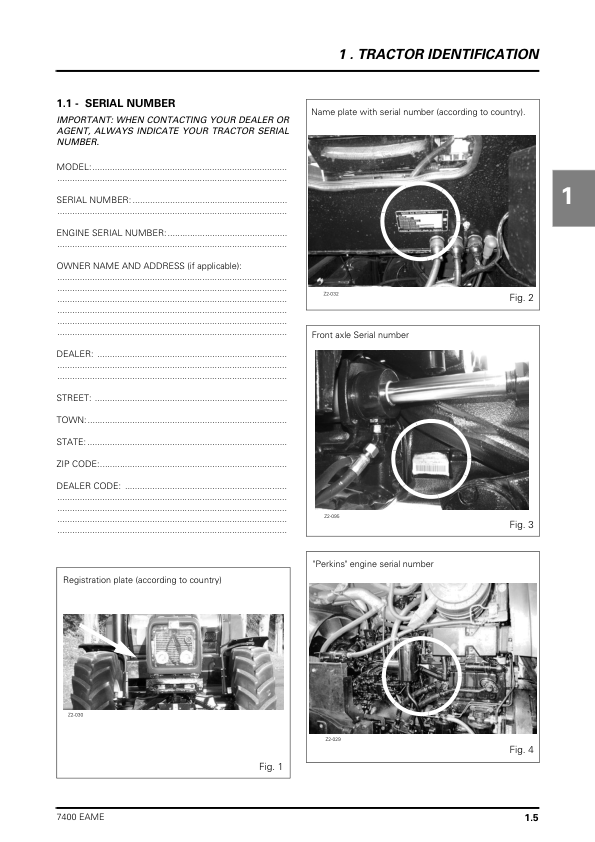
Before servicing the tractor, verify the model, engine and transmission configuration and confirm whether the relevant axle, braking or electronic equipment is installed. This helps ensure that the correct technical references are selected for component inspection, diagnosis and repair.

















Reviews
There are no reviews yet.