Overview
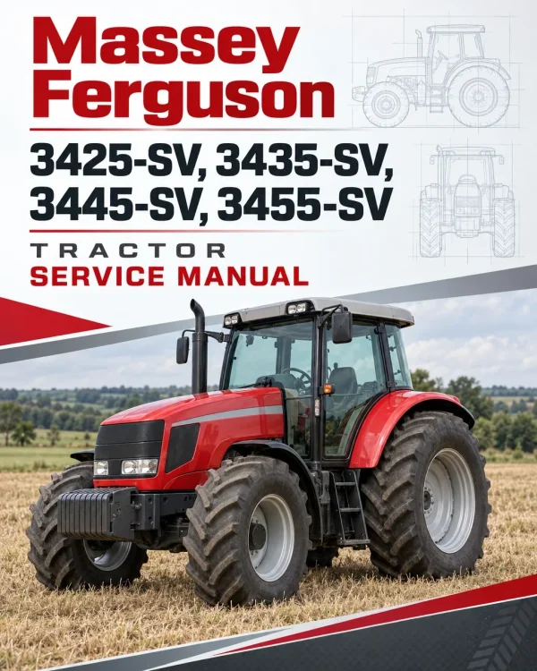
The Massey Ferguson 3400S/V Series Tractor Workshop Service Manual provides maintenance and repair information for the mechanical tractor range covering transmission assemblies, axles, brakes, power take-off equipment, hydraulic systems, electronic controls and electrical wiring.
Workshop coverage includes HML and non-HML gearbox arrangements, narrow and wide rear axle assemblies, hydraulic pump removal, clutch repairs and differential adjustments. The diagnostic section addresses All Round Tester (ART) connections, engine and lift control unit configuration, calibration and alarm interpretation. Separate electrical references distinguish governor types, cab and platform versions, and three-cylinder and four-cylinder engine wiring.
Notice: This publication is identified as MF3400 S/V Mechanical (not Power Shuttle). It is not a workshop manual for Power Shuttle versions.
Safety: Read the general safety rules, lifting instructions and removal/refitting precautions before carrying out the corresponding workshop operations.
Table of Contents
Massey Ferguson 3425S, 3425SV, 3435S, 3435V, 3445S, 3445V, 3455S, 3455V Manual
- 00. General Information, Safety and Workshop References
- General Safety Rules
- Safety Precautions for Removal and Refitting
- Lifting Instructions
- Manual Structure, Consultation and Updates
- Manual Symbols
- Standard Nut and Bolt Tightening Torques
- Fitting and Threaded Plug Tightening Torques
- 37-Degree Sealing Fittings
- Pipe Fittings with Eye Attachments
- Threadlockers, Adhesives, Sealants and Lubricants
- Measurement Conversion Factors
- 10. Mechanical Systems and Hydraulic Operation
- Transmission Housing
- HML Assembly
- Gearbox and Shuttle Assembly with HML
- Gearbox and Shuttle Assembly without HML
- Shuttle and Underdrive Control Rod
- Speed Control Rod
- Range and Parking Brake Assembly
- Range Control Rod and Parking Brake Lever
- Four-Wheel-Drive Engagement Assembly
- Transmission Differential Assembly
- Brakes and Rear Axle Assembly – Narrow Version
- Brakes and Rear Axle Assembly – Wide Version
- Rear PTO Control Clutch Assembly
- Two-Speed Rear PTO
- Two-Speed Rear PTO with Synchro PTO
- Three-Speed Rear PTO
- Four-Wheel-Drive Front Axle
- Front Lift
- Front PTO
- Steering and Services Hydraulic Circuit – Standard Version
- Steering and Services Hydraulic Circuit – HML Version
- Lift and Auxiliary Services Hydraulic Circuit – Standard Version
- Lift and Auxiliary Services Hydraulic Circuit – Four-Way Front Control Valve Version
- Lift and Auxiliary Services Hydraulic Circuit – Six-Way Front Control Valve Version
- Steering Circuit Gear Pump
- Lift Circuit Gear Pump – Standard Version, 22.5 cc/rev
- Lift Circuit Gear Pump – Full Version, 14+11 cc/rev
- Power Steering
- HML Solenoid Valve Assembly
- Auxiliary Services Control Valve – Rear and Front Four-Way Versions
- Auxiliary Services Control Valve – Rear Six-Way Version
- Auxiliary Services Control Valve – Front Six-Way Version
- Hydraulic Three-Point Linkage Control Valve
- Services Solenoid Valve Assembly
- Hydraulic Trailer Braking Valve
- Hydraulic Lift Control Valve
- 20. Electronic Diagnostics, Commissioning and Calibration
- All Round Tester (ART) Kit and Correct Use
- Tester Controls, Connections and Power Supply
- Tester Display Language and Serial Port Settings
- ART Connections to Engine and Lift Control Units
- Electronic Engine Control System
- Electronic Pre-Heating Control System
- HML Electronic Control System
- Electronic Lift Control Unit
- Engine Control Unit Replacement and Engine Type Configuration
- Hand Throttle Calibration
- Accelerator Pedal Calibration
- HML Configuration
- Pre-Heating Type Configuration
- Wheel Parameter Configuration
- Engine Idling Speed Calibration
- Engine Control Unit Alarm Cancellation
- Lift Control Unit Replacement and Maximum Lift Height Calibration
- Engine Alarm Indications – MEM Warning Light
- Engine Alarm Indications – Pre-Heating Indicator Light
- Engine Control Unit Alarms Displayed on ART
- Lift Control Alarms – Button Flash Sequences
- Lift Control Unit Alarms Displayed on ART
- Engine Control Unit Test Meter – Configuration, Calibration and Monitoring
- HML Diagnostic Menu – Configuration, Tests and Monitoring
- Pre-Heating Diagnostic Menu – Configuration, Tests and Monitoring
- Alarm Initialization and Alarm Log
- Wheel Calibration – Water-Cooled Engine Menu
- Belt Configuration, Tests and Monitoring – Air-Cooled Engine Menu
- Wheel Settings – Water-Cooled Engine Menu
- Wheel Monitoring – Air-Cooled Engine Menu
- PTO Calibration, Tests and Monitoring – Versions with Auto PTO
- Engine Type Reference List
- Lift Control Unit Test Meter – Initialization and Main Menu
- Lift Maximum Height and Raising Speed Calibration
- Lift, Draft and Position Monitoring
- Lift Sensor, Voltage and Input Tests
- Lift Control Unit Alarm Menu
- 30. Component Removal, Refitting, Repair and Adjustment
- Front Hood Removal and Refitting
- Front and Rear Wheel Removal and Refitting
- Safety Roll Bar Removal and Refitting
- Main Fuel Tank Removal and Refitting
- Supplementary Fuel Tank Draining, Removal and Refitting
- Radiator Removal and Refitting
- Front Support Removal and Refitting
- Four-Wheel-Drive Front Axle Removal and Refitting
- Front Axle Steering Cylinder Removal and Refitting
- Stub Axle Housing and Axle Shaft Removal and Refitting
- Stub Axle Bearing Preload Adjustment
- Front Epicyclic Reduction Unit Removal, Refitting, Disassembly and Assembly
- Front Pinion-Differential Assembly Removal and Refitting
- Front Differential Lock Removal, Refitting and Adjustment
- Front Bevel Gear Pair Disassembly and Assembly
- Front Pinion Position and Bearing Preload Adjustment
- Front Differential Bearing Preload Adjustment
- Front Pinion and Crownwheel Adjustment
- Front Differential Disassembly and Assembly
- Operator Platform Removal and Refitting
- Cab Removal and Refitting
- Front Axle Drive Shaft Removal and Refitting
- Engine and Transmission Separation Preparation
- Engine Removal and Refitting
- Clutch Plate Removal, Wear Inspection, Replacement and Refitting
- Clutch Release Bearing Replacement
- Starter Motor Removal and Refitting
- HML Unit Removal and Refitting
- HML Reduction Unit End Float Inspection
- HML Clutch Unit Disassembly and Assembly
- HML Planet Carrier Disassembly and Assembly
- Gearbox and Shuttle Assembly Removal, Refitting and Transmission Separation
- Gearbox and Shuttle Assembly Disassembly and Assembly
- Shuttle and Underdrive Shaft Disassembly and Assembly
- Transmission Primary Shaft Disassembly and Assembly
- Transmission Secondary Shaft Disassembly and Assembly
- Gear Selector Rod Disassembly and Assembly
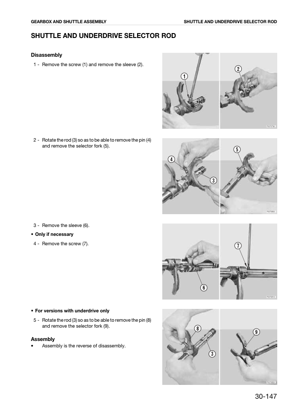
- Shuttle and Underdrive Selector Rod Disassembly and Assembly
- Four-Wheel-Drive Engagement Control Removal, Refitting, Disassembly and Assembly
- Steering Circuit and Solenoid Valve Pump Removal and Refitting
- Hydraulic Lift and Auxiliary Services Pump Removal and Refitting
- Hydraulic Trailer Braking Valve Removal and Refitting
- Hydraulic Lift Removal, Refitting, Disassembly and Assembly – Mechanical Governor Version
- Hydraulic Lift Bushing Replacement – Mechanical Governor Version
- Hydraulic Lift Control Valve Removal, Refitting, Disassembly and Assembly – Mechanical Governor Version
- Hydraulic Lift Cylinder Disassembly and Assembly – Mechanical Governor Version
- Mechanical Draft Sensor Removal, Refitting, Disassembly and Assembly
- Lift Control Lever Adjustment – Mechanical Governor Version
- Remote Control Valve Removal and Refitting
- Right and Left Rear Axle Removal Preparation
- Complete Rear Axle Removal and Refitting
- Rear Axle Disassembly and Assembly – Wide Version
- Rear Axle Disassembly and Assembly – Narrow Version
- Rear Axle Planet Carrier Disassembly and Assembly
- Rear Brake Disc Replacement
- Rear Brake Piston Disassembly and Assembly
- Front Brake Disc Removal and Refitting
- Front Brake Piston Disassembly and Assembly
- Parking Brake Friction Shoe Removal and Refitting
- Parking Brake Disassembly and Assembly
- Brake Cylinder Removal and Refitting
- Service Valve Assembly Removal, Refitting, Disassembly and Assembly
- Three-Point Linkage Removal and Refitting
- Towing Hitch Removal and Refitting
- Rear PTO Input Shaft Removal and Refitting
- Rear PTO Clutch Removal, Refitting, Disassembly and Assembly
- PTO Output Shaft Disassembly and Assembly – Two-Speed and Groundspeed Version
- Groundspeed PTO Drive Shaft Disassembly and Assembly
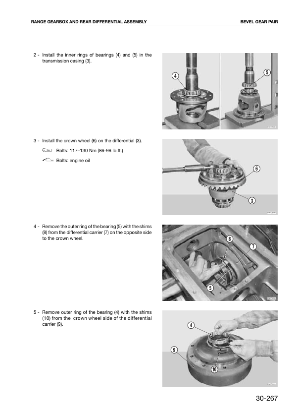
- Range Gearbox and Rear Differential Assembly Disassembly and Assembly
- PTO Pump Drive Disassembly and Assembly
- Rear Differential Unit Removal, Refitting, Disassembly and Assembly
- Rear Differential Pinion Disassembly and Assembly
- Range Selector Rod Disassembly and Assembly
- Four-Wheel-Drive and Groundspeed PTO Output Shaft Disassembly and Assembly
- Rear Bevel Gear Pair Adjustment Preparation
- Rear Differential Bearing Preload Adjustment
- Rear Pinion Position Adjustment
- Rear Pinion and Crownwheel Adjustment
- Instrument Panel Removal and Refitting
- Power Steering Unit Removal and Refitting
- Clutch Master Cylinder Removal and Refitting
- 40. Electrical Systems, Component Data and Wiring Diagrams
- Electrical Documentation Structure and Consultation
- Tractor Wiring Harness List
- Electrical Components and Symbols
- Electrical and Electronic Circuit Modification Precautions
- Common Wiring Faults
- Connector and Wiring Removal, Refitting and Drying
- Electrical Diagnostic Instruments
- Wire Colour Codes
- Component Description Index
- Component Code Index
- Connector Index
- Electrical Component Technical Data
- Engine Control Unit Pinouts – Code 2.8519.054.0/40
- HML Control Unit Pinouts – Code 0.010.8869.4/20, Mechanical Governor Versions Only
- Electronic Lift Control Unit Pinouts – Code 0.011.2992.4/30
- Pre-Heating Control Unit Pinouts – Code 2.8519.023.0/10, Mechanical Governor Versions Only
- Earthing Point Locations
- Starting and Pre-Heating Circuits – Electronic Governor, Cab Version
- Starting and Pre-Heating Circuits – Mechanical Governor, Cab Version
- Electronic Engine Control Circuit – Electronic Governor, Cab Version
- Lighting and Steering Column Switch Circuits – Electronic Governor, Cab Version
- Lighting and Steering Column Switch Circuits – Mechanical Governor, Cab Version
- Diagnostic Accessory Circuits – Electronic Governor, Cab and Platform Versions
- Diagnostic Accessory Circuits – Mechanical Governor, Cab and Platform Versions
- Instrument Panel Circuits – Electronic Governor, Cab Version
- Instrument Panel Circuits – Mechanical Governor, Cab Version
- Worklight Circuits – Electronic Governor, Cab and Platform Versions
- Worklight Circuits – Mechanical Governor, Cab and Platform Versions
- Windscreen Wiper Circuits – Electronic Governor, Cab Version
- Windscreen Wiper Circuits – Mechanical Governor Version
- Heating Circuits – Cab Versions with Electronic or Mechanical Governor
- Air Conditioning Circuits – Cab Versions with Electronic or Mechanical Governor
- Brake Circuits – Cab Versions with Electronic or Mechanical Governor
- HML Transmission Circuits – Cab Versions with Electronic or Mechanical Governor
- Electronic Lift Control Circuits – Cab Versions with Electronic or Mechanical Governor
- Front and Rear PTO Circuits – Cab Versions with Electronic or Mechanical Governor
- Front Control Valve Circuits – Cab Versions with Electronic or Mechanical Governor
- Three-Point Linkage Circuits – Cab Versions with Electronic or Mechanical Governor
- Battery Lead Wiring
- Central Wiring – Mechanical Governor Version
- Diagnostic Socket Wiring
- Rear Wiring – Mechanical Governor Version
- Rear Wiring Harness
- Central Wiring – Electronic Governor Version
- Rear Wiring – Electronic Governor Version
- Engine Wiring – Three-Cylinder Version
- Engine Wiring – Four-Cylinder Version
- Rotating Beacon Wiring
- Cab Light Wiring
- Front PTO Wiring
- Safety Roll Bar Light Wiring
- Pre-Heating and Supply Wiring – Three-Cylinder Cab Version
- Pre-Heating and Supply Wiring – Four-Cylinder Cab Version
- Pre-Heating and Supply Wiring – Three-Cylinder Platform Version
- Pre-Heating and Supply Wiring – Four-Cylinder Platform Version
- Electronic Lift Wiring
- Roof Wiring
- Cab Power Supply Wiring
- Windscreen Wiper Wiring
- Heater Wiring
- Air Conditioning System Wiring
- Air Conditioning Fan Wiring
- Worklight, Rear Window Wiper and Flashing Light Wiring
- Earth Wiring
- Front Control Valve Wiring
- Front Control Valve Solenoid Wiring
- Three-Point Linkage Wiring
Matching Electrical Diagrams to Governor and Cab Versions
The electrical section separates mechanical-governor and electronic-governor circuits, with further cab and platform distinctions for diagnostic accessories, worklights and pre-heating equipment. Match these configuration labels before consulting the associated circuit diagrams and wiring references.
Three-cylinder and four-cylinder engine harnesses also have separate entries. The HML and pre-heating control-unit pinouts marked for mechanical-governor versions are configuration-specific, rather than universal references for every tractor covered by the publication.





















Reviews
There are no reviews yet.