Overview
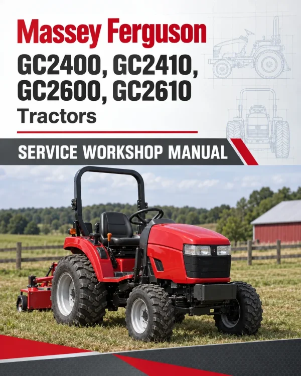
The Massey Ferguson GC2400, GC2410, GC2600 and GC2610 Compact Tractor Workshop Service Manual provides technical information for servicing, maintaining and repairing these GC Series tractors. It includes component identification, system diagrams, inspection procedures, mechanical adjustments and workshop instructions for major tractor assemblies.
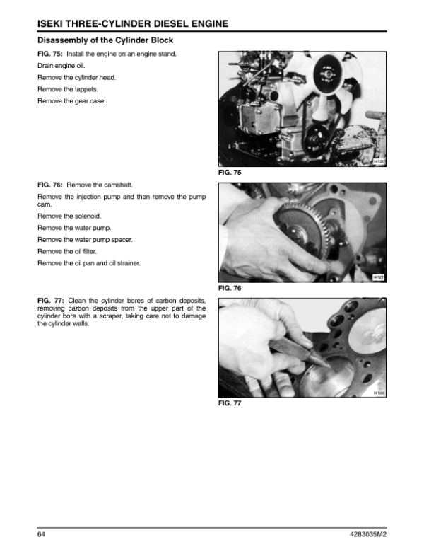
Coverage includes chassis components, engine cooling and fuel systems, transmission and hydrostatic drive assemblies, front and rear axles, brakes, hydraulics, steering and electrical equipment. A dedicated mower deck chapter addresses installation, removal, linkage adjustment, lubrication, cutting components and gearbox servicing.
Safety: The chassis documentation includes rollover protection system (ROPS) servicing, while the mower deck chapter identifies safety and cutting-height adjustment labels. Review the applicable instructions and equipment safety information before servicing these assemblies.
Notice: The supplied bookmarks identify an engine manual insertion and a separate Engine entry without detailing the engine overhaul chapters. Confirm the included engine documentation in the manual before relying on it for engine-specific repairs.
Table of Contents
Massey Ferguson GC2400, GC2410, GC2600, GC2610 Manual
- Introduction
-
Chassis
- Roll Over Protection System (ROPS)
- Platform and Sheet Metal
- Removal and Installation of Seat
- Removal and Installation of Transmission
- Engine
- Engine
-
Cooling, Air and Fuel
- Service Access
- Cooling System
- Thermostat
- Engine Air Cleaner
- Fuel System
-
Transmission
- Ground Speed Selection
- Hydrostatic Transmission
- Transmission and Related Parts
- Transmission
- PTO
- PTO Clutch
- Rear PTO
- Shift Linkages
- Assembly of Transmission
-
Hydrostatic Transmission
- Components
- HST
- Adjustment of HST
- Function
- Valves
- Disassembly and Assembly
- Criteria for Replacing Worn Parts
- Precautions Before Assembly
- Assembly
- Troubleshooting
-
Rear Axle and Brakes
- Assembly Guidelines
- Differential Lock
- Brakes and Axles
- Inspection
- Brake Adjustment
-
Front Axle
- Components Layout
- Disassembly and Assembly
-
Hydraulic System
- Hydraulic Specifications
- Components and Test Ports
- Joystick Valve (Factory Installed)
- Operation Mechanism
- Control Valve
- Lift Cylinder Assembly
- Steering
-
Electrical
- Wire Harness
- Electrical System
- Wiring Diagram
- Electrical Components and Switches
- Instrument Panel
-
Mower Deck
- General Information
- Mower Deck Installation
- Linkage Adjustment
- Mower Deck Removal
- Lubrication and Maintenance
- Gearbox
Hydrostatic Drive and Mower Deck Service Information
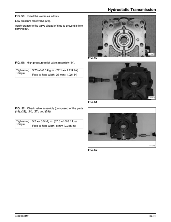
The hydrostatic transmission chapter provides information about the HST components, operating principles, valves, adjustments, disassembly, reassembly and troubleshooting. It also includes inspection criteria for worn parts, while the main transmission chapter covers ground speed selection, PTO components, clutch assemblies and shift linkages.
The mower deck documentation covers mounting and removal, lift linkage adjustment, lubrication, belt inspection, blade servicing and gearbox maintenance. Hydraulic system information includes component test ports, joystick and control valves, lift cylinder assemblies and steering components. Consult the relevant specifications and procedures for the tractor and equipment being serviced.

















Reviews
There are no reviews yet.