Overview
The Massey Ferguson 3425S, 3435S, 3445S and 3455S Series S Tractor Workshop Service Manual provides service, diagnostic and repair information for the MF 3400 S tractors equipped with Power Shuttle. Publication 1857670M1 is supplied as a 717-page manual covering mechanical and hydraulic transmission systems, PTO and axle assemblies, steering, electronic controls, workshop repairs and electrical wiring.
The contents distinguish Power Shuttle and HML gearbox configurations, front and rear axle arrangements, lift and auxiliary hydraulic circuits, engine and shuttle ECU configuration, clutch calibration and diagnostic alarm codes. Workshop procedures also cover transmission shafts, forward and reverse shuttle clutches, brakes, linkage, hydraulic pumps, and model-specific electrical harnesses for cab or platform and three- or four-cylinder versions.
Notice: This is the MF3400 S manual with Power Shuttle, not the separate MF3400 S/V mechanical-transmission manual. The index includes HML and non-HML variants, cab and platform wiring, and multiple hydraulic configurations; follow the procedures matching the installed equipment.
Safety: Review the manual’s safety notes, lifting instructions, and precautions for removal and refitting before performing the relevant workshop operations.
Table of Contents
Massey Ferguson 3425S, 3435S, 3445S, 3455S Manual
-
00. General Information, Safety and Workshop References
- Safety Notes and General Workshop Precautions
- Safety Precautions for Removal and Refitting Operations
- Lifting Instructions and Wire Rope Slings
- How the Workshop Manual Is Structured
- Consulting Removal and Refitting Instructions
- Special Workshop Tools Reference
- Manual Updating and Inserting Updates
- Symbols Used in the Manual
- Standard Tightening Torques for Bolts and Nuts
- Tightening Torques for Fittings and Plugs
- 37-Degree Sealing Fittings
- Pipe Fittings with Eye Attachments
- Threadlockers, Adhesives, Sealants and Lubricants
- British-to-Metric and Metric-to-British Conversion Factors
-
10. Transmission, PTO and Hydraulic System Descriptions
- Power Shuttle Transmission – Construction and Operating Description
- Power Shuttle Unit
- HML Assembly
- Gearbox Assembly – Version with HML
- Gearbox and Shuttle Assembly – Version without HML
- Underdrive Control Rod and Speed Control Rod
- Range Gears and Parking Brake Assembly
- Range Control Rod and Parking Brake Lever
- Four-Wheel-Drive Engagement Assembly
- Transmission Differential Assembly
- Brakes and Rear Axle Assembly – Narrow Version
- Brakes and Rear Axle Assembly – Wide Version
- Rear PTO Control Clutch Assembly and Operation
- Two-Speed Rear PTO
- Two-Speed and Synchro Rear PTO
- Three-Speed Rear PTO
- Four-Wheel-Drive Front Axle
- Front Axle Final Drive – Version with Brakes
- Front Axle Final Drive – Version without Brakes
- Front Axle Pinion, Differential and Differential Lock
- Front Lift Main Components and Shock Absorber Unit
- Front PTO Description and Operation
- Steering and Services Hydraulic Circuit
- Steering, Services and HML Hydraulic Circuit
- Hydraulic Lift and Auxiliary Services Circuit – Standard Version
- Hydraulic Lift and Auxiliary Services Circuit – Four-Way Front Control Valve Version
- Hydraulic Lift and Auxiliary Services Circuit – Six-Way Front Control Valve Version
- Steering Circuit Gear Pump
- Lift Circuit Gear Pump – Standard Version, 22.5 cc/rev
- Lift Circuit Gear Pump – Full Version, 14+11 cc/rev
- Power Steering
- Cooler Bypass Assembly – With and Without HML
- Shuttle Solenoid Valve Assembly
- Auxiliary Services Control Valve – Rear and Front Four-Way Versions
- Auxiliary Services Control Valve – Rear Six-Way Version
- Auxiliary Services Control Valve – Front Six-Way Version
- Hydraulic Three-Point Linkage Control Valve
- Services Solenoid Valve Assembly
- Trailer Braking Valve – Italian Version
- Trailer Braking Valve – Export Version
- Hydraulic Lift Control Valve
-
20. Electronic Diagnostics, Power Shuttle Calibration and Alarms
- All Round Tester (ART) Diagnostic Kit and Operating Notes
- ART Tester Controls, Power Connections and Display Language
- ART Serial Port Configuration
- ART Connections to Engine and Hydraulic Lift Control Units
- Electronic Engine Control and Pre-Heating Systems
- Hydraulic Shuttle Electronic Control System
- HML Electronic Control System
- Instrument Panel and Electronic Lift Control Unit
- CAN Bus Communication System
- Engine ECU Replacement and Engine Type Configuration
- Hand Throttle and Accelerator Pedal Calibration
- Engine Pre-Heating Type and Wheel Parameter Configuration
- Engine Idle Speed Calibration and Alarm Cancellation
- Shuttle ECU Replacement and Initialization
- Shuttle ECU Gearbox Type Configuration
- Shuttle ECU Clutch Pedal Calibration
- Shuttle ECU Optional Equipment Configuration
- Shuttle ECU Alarm Cancellation
- Shuttle Clutch Calibration Parameters and Manual Settings
- Automatic Calibration of Power Shuttle Clutches
- Manual Calibration of Power Shuttle Clutches
- Instrument Panel Replacement and Tractor Type Programming
- Wheel Constant Entry and Speed Conversion Factor Settings
- Lift ECU Replacement and Maximum Lift Height Calibration
- Engine ECU Alarms – Instrument Panel and Pre-Heating Indicator
- Engine ECU Alarms – ART Display
- Shuttle ECU Alarms – Instrument Panel and ART Display
- Instrument Panel Alarms – Alarm Lamp and ART Display
- Electronic Lift ECU Alarms – Lift Control Button Flash Sequences
- Electronic Lift ECU Alarms – ART Display
- Lift ECU Flash Codes 11, 12, 13, 14 and 15
- Lift ECU Flash Codes 21, 22 and 23
- Lift ECU Flash Codes 41, 42, 45 and 50
-
30. Component Removal, Repair, Refitting and Adjustments
- Front Hood and Side Panel Removal and Refitting
- Front and Rear Wheel Removal and Refitting
- Safety Roll Bar Removal and Refitting
- Main Fuel Tank Removal and Refitting
- Supplementary Fuel Tank Draining, Removal and Refitting
- Radiator and Front Support Removal and Refitting
- Four-Wheel-Drive Front Axle Removal and Refitting
- Front Axle Steering Cylinder Removal and Refitting
- Steering Knuckle Housing and Half-Shaft Removal and Refitting
- Steering Knuckle Bearing Preload Adjustment
- Front Epicyclic Reduction Unit Removal and Overhaul
- Front Pinion–Differential Assembly Removal and Refitting
- Front Differential Lock Removal, Refitting and Adjustment
- Front Bevel Gear Pair and Pinion Bearing Preload Adjustment
- Front Differential Bearing Preload Adjustment
- Front Pinion and Crownwheel Adjustment
- Front Differential Disassembly and Assembly
- Operator Platform and Cab Removal and Refitting
- Front Axle Drive Shaft Removal and Refitting
- Engine Separation from Transmission and Engine Refitting
- Starter Motor Removal and Refitting
- Torsional Spring Plate Removal and Refitting
- Power Shuttle Unit Removal and Refitting
- Power Shuttle Unit Disassembly and Assembly
- Power Shuttle Cover Disassembly and Assembly
- Forward Drive Clutch Disassembly and Assembly
- Reverse Drive Clutch Disassembly and Assembly
- HML Unit Removal and Refitting
- HML Reduction Unit End Float Inspection
- HML Clutch Unit Disassembly and Assembly
- HML Planet Carrier Disassembly and Assembly
- Gearbox and Shuttle Assembly – Version without HML
- Gearbox and Shuttle Assembly – Version with HML
- Gearbox Input Shaft Disassembly and Assembly
- Transmission Primary Shaft Disassembly and Assembly
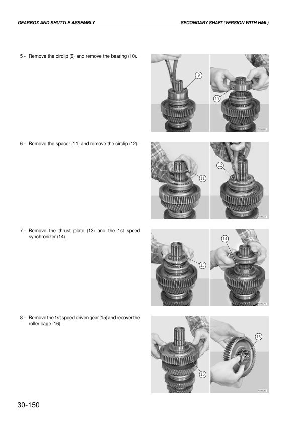
- Transmission Secondary Shaft – Version with HML
- Transmission Secondary Shaft – Version without HML
- Gear Selector Rod Disassembly and Assembly
- Mini-Reduction Gear Control Rod Disassembly and Assembly
- Four-Wheel-Drive Engagement Control Removal and Overhaul
- Steering Pump and Solenoid Valve Removal and Refitting
- Hydraulic Lift and Auxiliary Services Pump Removal and Refitting
- Hydraulic Service Valve Assembly Overhaul
- Hydraulic Trailer Braking Valve Removal and Refitting
- Hydraulic Lift Assembly – Mechanical Governor Version
- Hydraulic Lift Bushing Replacement – Mechanical Governor Version
- Hydraulic Lift Control Valve Overhaul – Mechanical Governor Version
- Hydraulic Lift Cylinder Disassembly and Assembly – Mechanical Governor Version
- Mechanical Draft Sensor Removal and Overhaul
- Hydraulic Lift Control Lever Adjustments
- Auxiliary Services Control Valve Removal and Refitting
- Rear Axle Removal and Refitting
- Rear Axle Disassembly and Assembly – Wide Version
- Rear Axle Disassembly and Assembly – Narrow Version
- Rear Planet Carrier Disassembly and Assembly
- Rear Axle Brake Disc Replacement
- Brake Piston Disassembly and Assembly
- Front Axle Brake Disc and Piston Servicing
- Parking Brake Friction Shoe Replacement
- Parking Brake Disassembly and Assembly
- Brake Cylinder Removal and Refitting
- Three-Point Linkage Removal and Refitting
- Towing Hitch Removal and Refitting
- Rear PTO Input Shaft Removal and Refitting
- Rear PTO Clutch Removal, Overhaul and Refitting
- Two-Speed and Groundspeed PTO Output Shaft Overhaul
- Groundspeed PTO Drive Shaft Overhaul
- Range Gearbox and Rear Differential Assembly Overhaul
- PTO Pump Drive Overhaul
- Rear Differential Unit Removal and Overhaul
- Rear Differential Pinion Disassembly and Assembly
- Range Selector Rod Disassembly and Assembly
- 4WD and Groundspeed PTO Output Shaft Overhaul
- Rear Bevel Gear Pair Adjustment Preparation
- Rear Differential Bearing Preload Adjustment
- Rear Pinion Position and Crownwheel Adjustment
- Instrument Panel Removal and Refitting
- Hydrostatic Steering Valve Removal and Refitting
-
40. Electrical Systems, Electronic Controls and Wiring
- Electrical Unit Structure and Wiring Diagram Navigation
- Wiring Harness List
- Electrical Component Definitions and Symbols
- Precautions for Modifying Tractor Electrical and Electronic Circuits
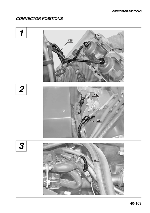
- Common Wiring Faults and Connector Servicing
- Electrical Diagnostic Instruments and Wire Colour Codes
- Electrical Part Description, Part Code and Connector Indices
- Electrical Component Technical Data
- Engine ECU Pinouts – Code 2.8519.054.0/60
- Electronic Lift ECU Pinouts – Code 0.011.2992.4/50
- Shuttle Control Unit Pinouts – Code 2.8519.030.0/60
- Instrument Panel Pinouts – Code 2.8339.248.0/20
- Electrical Earthing Point Locations
- Starting and Pre-Heating Circuits
- Electronic Engine Control Circuits
- Lighting and Steering Column Switch Circuits
- Diagnostic Accessories – Cab Version
- Diagnostic Accessories – Platform Version
- Instrument Panel Circuits
- Worklights – Cab and Platform Versions
- Windscreen Wiper Circuits
- Heating and Air Conditioning Circuits
- Brake System Electrical Circuits
- HML Transmission Electrical Circuits
- Electronic Lift and Front/Rear PTO Circuits
- Front Remote Valve and Three-Point Linkage Circuits
- CAN Bus Electrical System
- Battery Lead and Central Wiring
- Power Shuttle Lever Wiring
- Rear Wiring and Trailer Brake Wiring
- Filter and Interference Suppressor Wiring
- Engine Wiring – Three-Cylinder Version
- Engine Wiring – Four-Cylinder Version
- Rotating Beacon and Cab Light Wiring
- Front PTO and Roll Bar Lighting Wiring
- Pre-Heating and Power Supply – Three-Cylinder Cab Version
- Pre-Heating and Power Supply – Four-Cylinder Cab Version
- Pre-Heating and Power Supply – Three-Cylinder Platform Version
- Pre-Heating and Power Supply – Four-Cylinder Platform Version
- Roof and Cab Power Supply Wiring
- Windscreen Wiper, Heater and Air Conditioning Wiring
- Air Conditioning Fan Wiring
- Worklight, Rear Window Wiper and Flashing Light Wiring
- Earth Wiring and Electronic Lift Wiring
- Front Control Valve and Solenoid Wiring
- Three-Point Linkage Wiring
Power Shuttle Calibration and Configuration-Specific Wiring
The diagnostic section separately identifies the engine ECU, shuttle ECU, instrument panel and lift ECU. Power Shuttle servicing includes clutch-pedal calibration, automatic and manual shuttle clutch calibration, and gearbox-type configuration. These procedures are indexed separately from the mechanical repair instructions for the forward and reverse drive clutch assemblies.
The wiring section identifies the shuttle control unit and CAN bus alongside separate three- and four-cylinder engine harnesses and cab/platform pre-heating connections. Use the relevant ECU and wiring identifiers, together with the tractor’s HML arrangement, when selecting a diagnostic or assembly reference.
























Reviews
There are no reviews yet.