Overview
The Massey Ferguson 5425, 5435, 5445, 5460, 5465, 5470, 5475 and 5480 Tractor Workshop Manual provides technical references for servicing and repairing 5400 Series tractors. It includes component layouts, electrical and hydraulic diagrams, diagnostic information and procedures for adjustments, disassembly and reassembly.
Coverage spans Sisu and Perkins engines, GBA50 gearbox configurations, GPA50 rear axle and braking assemblies, front axles, power take-off equipment and open-centre hydraulics. Further chapters address the electrical system, cab air conditioning, suspension and specialized service tools.
Notice: The Clutch, Electronics and Accessories chapters are marked “intentionally left blank” in the supplied contents. No individual procedures are listed under those headings.
Table of Contents
Massey Ferguson 5425, 5435, 5445, 5460, 5465, 5470, 5475, 5480 Manual
-
1. Introduction
- 1A10 – 5400 series tractors – General
- 1A11 – 5400 series tractors – Error codes
- 1A12 – 5400 series tractors – Fuse box, electrical diagrams, harnesses and hydraulics diagrams
- 1A16 – 5400 series tractors – Adjustments, bleeding and calibrations
-
2. Separation of assemblies
- 2A17 – Cab – Disassembly and reassembly
-
3. Engine
- 3A10 – Sisu Tier 3 engine – General
- 3A13 – Sisu Tier 3 engine – Layout of components
- 3A14 – Sisu Tier 3 engine – Tests and diagnostics
- 3A16 – Sisu Tier 3 engine – Adjustments, bleeding and calibrations
- 3A17 – Sisu Tier 3 engine – Disassembly and reassembly
- 3A18 – Sisu Tier 3 engine – Service tools
- 3B10 – Perkins 1104D Tier 3 mechanical engine
- 3B20 – Perkins 1104D Tier 3 electronic engine
- 1104D Industrial Engine
-
4. Clutch
-
5. Gearbox
- 5A10 – GBA50 – General information
- 5A12 – GBA50 – Electrical and hydraulics diagrams
- 5A13 – GBA50 – Layout of components
- 5A16 – GBA50 – Adjustments, bleeding and calibrations
- 5A17 – GBA50 – Disassembly/reassembly
- 5A20 – GBA50/Power Shuttle – General information
- 5A22 – GBA50/Power Shuttle – Electrical and hydraulics diagrams
- 5A23 – GBA50/Power Shuttle – Layout of components
- 5A27 – GBA50/Power Shuttle – Disassembly/reassembly
- 5A28 – GBA50/Power Shuttle – Service tools
- 5A30 – GBA50/Powershift module – General information
- 5A32 – GBA50/Powershift module – Electrical and hydraulics diagrams
- 5A33 – GBA50/Powershift module – Layout of components
- 5A37 – GBA50/Powershift module – Disassembly/reassembly
- 5A38 – GBA50/Powershift module – Service tools
- 5A40 – GBA50/Robotic mechanical gearbox – General information
- 5A42 – GBA50/Robotic mechanical gearbox – Electrical and hydraulics diagrams
- 5A43 – GBA50/Robotic mechanical gearbox – Layout of components
- 5A47 – GBA50/Robotic mechanical gearbox – Disassembly/reassembly
- 5A48 – GBA50/Robotic mechanical gearbox – Service tools
- 5A60 – GBA50/Super creeper gears – General
- 5A63 – GBA50/Super creeper gears – Layout of components
- 5A66 – GBA50/Super creeper gears – Adjustments, bleeding and calibrations
- 5A67 – GBA50/Super creeper gears – Disassembly/reassembly
- 5A68 – GBA50/Super creeper gears – Service tools
-
6. Rear axle
- 6A10 – GPA50 – General information
- 6A12 – GPA50 – Electrical and hydraulics diagrams
- 6A13 – GPA50 – Layout of components
- 6A17 – GPA50 – Disassembly/reassembly
- 6A20 – GPA50/Trumpet housings – General information
- 6A22 – GPA50/Trumpet housings – Electrical and hydraulics diagrams
- 6A23 – GPA50/Trumpet housings – Layout of components
- 6A26 – GPA50/Trumpet housings – Adjustments, bleeding and calibrations
- 6A27 – GPA50/Trumpet housings – Disassembly/reassembly
- 6A28 – GPA50/Trumpet housings – service tools
- 6A30 – GPA50/Rear crown wheel and pinion 9×40 and 10×42 – General
- 6A32 – GPA50/Rear crown wheel and pinion 9×40 and 10×42 – Electrical and hydraulics diagrams
- 6A33 – GPA50/Rear crown wheel and pinion 9×40 and 10×42 – Layout of components
- 6A36 – GPA50/Rear crown wheel and pinion 9×40 and 10×42 – Adjustments, bleeding and calibrations
- 6A37 – GPA50/Rear crown wheel and pinion 9×40 and 10×42 – Disassembly/reassembly
- 6A38 – GPA50/Rear crown wheel and pinion 9×40 and 10×42 – Service tools
- 6A40 – GPA50/Tractor braking – General information
- 6A42 – GPA50/Tractor braking – Electrical and hydraulics diagrams
- 6A43 – GPA50/Tractor braking – Layout of components
- 6A46 – GPA50/Tractor braking – Adjustments, bleeding and calibrations
- 6A47 – GPA50/Tractor braking – Disassembly/reassembly
- 6A48 – GPA50/Tractor braking – Service tools
- 6A50 – GPA50/Hydraulic trailer braking – General
- 6A52 – GPA50/Hydraulic trailer braking – Electrical and hydraulics diagrams
- 6A53 – GPA50/Hydraulic trailer braking – Layout of components
- 6A56 – GPA50/Hydraulic trailer braking – Adjustments, bleeding and calibrations
- 6A57 – GPA50/Hydraulic trailer braking – Disassembly/reassembly
- 6A58 – GPA50/Hydraulic trailer braking – Service tools
-
7. Power take-off
- 7A10 – GPA50/Rear PTO with two electrohydraulic speeds – General
- 7A12 – GPA50/Rear PTO with two electrohydraulic speeds – Electrical and hydraulics diagrams
- 7A13 – GPA50/Rear PTO with two electrohydraulic speeds – Layout of components
- 7A16 – GPA50/Rear PTO with two electrohydraulic speeds – Adjustments, bleeding and calibrations
- 7A17 – GPA50/Rear PTO with two electrohydraulic speeds – Disassembly/reassembly
- 7A18 – GPA50/Rear PTO with two electrohydraulic speeds – Service tools
- 7A20 – GPA50/Rear PTO with three electrohydraulic speeds – General
- 7A22 – GPA50/Rear PTO with three electrohydraulic speeds – Electrical and hydraulics diagrams
- 7A23 – GPA50/Rear PTO with three electrohydraulic speeds – Layout of components
- 7A26 – GPA50/Rear PTO with three electrohydraulic speeds – Adjustments, bleeding and calibrations
- 7A27 – GPA50/Rear PTO with three electrohydraulic speeds – Disassembly/reassembly
- 7A28 – GPA50/Rear PTO with three electrohydraulic speeds – Service tools
- 7A30 – GPA50/Rear power take-off clutch – General
- 7A32 – GPA50/Rear power take-off clutch – Electrical and hydraulics diagrams
- 7A33 – GPA50/Rear power take-off clutch – Layout of components
- 7A37 – GPA50/Rear power take-off clutch – Disassembly/reassembly
- 7A38 – GPA50/Rear power take-off clutch – Service tools
- 7C10 – Zuidberg front power take-off – General
- 7C11 – Zuidberg front power take-off – Error codes
- 7C12 – Zuidberg front power take-off – Electrical and hydraulics diagrams
- 7C13 – Zuidberg front power take-off – Layout of components
- 7C14 – Zuidberg front power take-off – Tests and diagnostics
- 7C15 – Zuidberg front power take-off – Programming and setting parameters
- 7C16 – Zuidberg front power take-off – Adjustments, bleeding and calibrations
- 7C17 – Zuidberg front power take-off – Disassembly and reassembly
- 7C18 – Zuidberg front power take-off – Service tools
-
8. Front axle
- 8A10 – DANA 720 – General information
- 8A12 – DANA 720 – Electrical and hydraulics diagrams
- 8A13 – DANA 720 – Layout of components
- 8A14 – DANA 720 – Tests and diagnostics
- 8A17 – DANA 720 – Disassembly and reassembly
- 8A18 – DANA 720 – Service tools
- 8B10 – DANA 725 – General information
- 8B12 – DANA 725 – Electrical and hydraulics diagrams
- 8B13 – DANA 725 – Layout of components
- 8B14 – DANA 725 – Tests and diagnostics
- 8B17 – DANA 725 – Disassembly and reassembly
- 8B18 – DANA 725 – Service tools
- 8C10 – DANA 730 fixed – General information
- 8C12 – DANA 730 fixed – Electrical and hydraulics diagrams
- 8C13 – DANA 730 fixed – Layout of components
- 8C14 – DANA 730 fixed – Tests and diagnostics
- 8C17 – DANA 730 fixed – Disassembly and reassembly
- 8C18 – DANA 730 fixed – Service tools
- 8C20 – DANA 730 suspended – General information
- 8C21 – DANA 730 suspended – Error codes
- 8C22 – DANA 730 suspended – Electrical and hydraulics diagrams
- 8C23 – DANA 730 suspended – Layout of components
- 8C24 – DANA 730 suspended – Tests and diagnostics
- 8C27 – DANA 730 suspended – Disassembly and reassembly
- 8C28 – DANA 730 suspended – Service tools
- 8D10 – DANA 735 fixed – General information
- 8D11 – DANA 735 fixed – Error codes
- 8D12 – DANA 735 – Electrical and hydraulics diagrams
- 8D13 – DANA 735 fixed – Layout of components
- 8D14 – DANA 735 fixed – Tests and diagnostics
- 8D17 – DANA 735 fixed – Disassembly and reassembly
- 8D18 – DANA 735 fixed – Service tools
- 8D20 – DANA 735 suspended – General information
- 8D21 – DANA 735 suspended – Error codes
- 8D22 – DANA 735 suspended – Electrical and hydraulics diagrams
- 8D23 – DANA 735 suspended – Layout of components
- 8D24 – DANA 735 suspended – Tests and diagnostics
- 8D27 – DANA 735 suspended – Disassembly and reassembly
- 8D28 – DANA 735 suspended – Service tools
- 8G10 – GPA50/4WD clutch – General information
- 8G12 – GPA50/4WD clutch – Electrical and hydraulics diagrams
- 8G13 – GPA50/4WD clutch – Layout of components
- 8G16 – GPA50/4WD clutch – Adjustments, bleeding and calibrations
- 8G17 – GPA50/4WD clutch – Disassembly and reassembly
- 8G18 – GPA50/4WD clutch – Service tools
- 8I10 – Open Centre/Steering unit – General
-
9. Hydraulics
- 9A10 – GTA5050 open centre – General
- 9A12 – GTA5050 open centre – Electrical and hydraulics diagrams
- 9A13 – GTA5050 open centre – Layout of components
- 9A14 – GTA5050 open centre – Tests and diagnostics
- 9A20 – GTA5050 open centre/right-hand cover plate – General
- 9A22 – GTA5050 open centre/right-hand cover plate – Electrical and hydraulics diagrams
- 9A23 – GTA5050 open centre/right-hand cover plate – Layout of components
- 9A27 – GTA5050 open centre/right-hand cover plate – Disassembly/reassembly
- 9B10 – GTA5050 100 l/min open centre – General
- 9B12 – GTA5050 100 l/min open centre – Electrical and hydraulics diagrams
- 9B13 – GTA5050 100 l/min open centre – Layout of components
- 9B14 – GTA5050 100 l/min open centre – Tests and diagnostics
- 9B20 – GTA5050 100 l/min open centre/right-hand cover plate – General
- 9B22 – GTA5050 100 l/min open centre/right-hand cover plate – Electrical and hydraulics diagrams
- 9B23 – GTA5050 100 l/min open centre/right-hand cover plate – Layout of components
- 9B27 – GTA5050 100 l/min open centre/right-hand cover plate – Disassembly/reassembly
- 9B30 – GTA5050 100 l/min open centre/left-hand cover plate – General
- 9B32 – GTA5050 100 l/min open centre/left-hand cover plate – Electrical and hydraulics diagrams
- 9B33 – GTA5050 100 l/min open centre/left-hand cover plate – Layout of components
- 9B37 – GTA5050 100 l/min open centre/left-hand cover plate – Disassembly/reassembly
- 9C10 – GTA5050 open centre/spool valves – General
- 9C12 – GTA5050 open centre/spool valves – Electrical and hydraulics diagrams
- 9C13 – GTA5050 open centre/spool valves – Layout of components
- 9C17 – GTA5050 open centre/spool valves – Disassembly/reassembly
- 9C20 – GTA5050 open centre/rear linkage – General
- 9C22 – GTA5050 open centre/rear linkage – Electrical and hydraulics diagrams
- 9C23 – GTA5050 open centre/rear linkage – Layout of components
- 9C24 – GTA5050 open centre/rear linkage – Tests and diagnostics
- 9C27 – GTA5050 open centre/rear linkage – Disassembly/reassembly
- 9C30 – GTA5050 open centre/front linkage – General
- 9C32 – GTA5050 open centre/front linkage – Electrical and hydraulics diagrams
- 9C33 – GTA5050 open centre/front linkage – Layout of components
- 9C36 – GTA5050 open centre/front linkage – Adjustments, bleeding and calibrations
- 9C37 – GTA5050 open centre/front linkage – Disassembly/reassembly
- 9D10 – GPA50/Brake master cylinders – General
- 9D12 – GPA50/Brake master cylinders – Electrical and hydraulics diagrams
- 9D13 – GPA50/Brake master cylinders – Layout of components
- 9D16 – GPA50/Brake master cylinders – Adjustments, bleeding and calibrations
- 9D17 – GPA50/Brake master cylinders – Disassembly/reassembly
- 9D18 – GPA50/Brake master cylinders – Service tools
- 9D20 – GPA50/Hydraulic trailer braking – General
- 9D22 – GPA50/Hydraulic trailer braking – Electrical and hydraulics diagrams
- 9D23 – GPA50/Hydraulic trailer braking – Layout of components
- 9D26 – GPA50/Hydraulic trailer braking – Adjustments, bleeding and calibrations
- 9D27 – GPA50/Hydraulic trailer braking – Disassembly/reassembly
- 9D28 – GPA50/Hydraulic trailer braking – Service tools
-
10. Electricity
- 10A12 – Lighting and equipment – Electrical diagrams
- 10A13 – Lighting and equipment – Layout of components
- 10B10 – Fuse box – General
- 10B12 – Fuse box – Electrical and hydraulics diagrams
- 10B13 – Fuse box – Layout of components
- 10B17 – Fuse box – Disassembly and reassembly
- 10C14 – Alternator – Tests and diagnostics
- 10C17 – Alternator – Disassembly and reassembly
- 10C18 – Alternator – Service tools
- 10E10 – Starter – General
- 10E14 – Starter – Tests and diagnostics
- 10E17 – Starter – Disassembly and reassembly
-
11. Electronics
-
12. Cab
- 12A10 – Standard air conditioning – General
- 12A12 – Standard air conditioning – Electrical and hydraulics diagrams
- 12A14 – Standard air conditioning – Tests and diagnostics
- 12A16 – Standard air conditioning – Adjustments, bleeding and calibrations
- 12B10 – Cab suspension – General
- 12B12 – Cab suspension – electrical and hydraulics diagrams
- 12B13 – Cab suspension – Layout of components
- 12B17 – Cab suspension – Disassembly and reassembly
-
13. Accessories
-
14. Service tools
- 14A01 – General
- 14A03 – Engine
Selecting the Applicable System Configuration
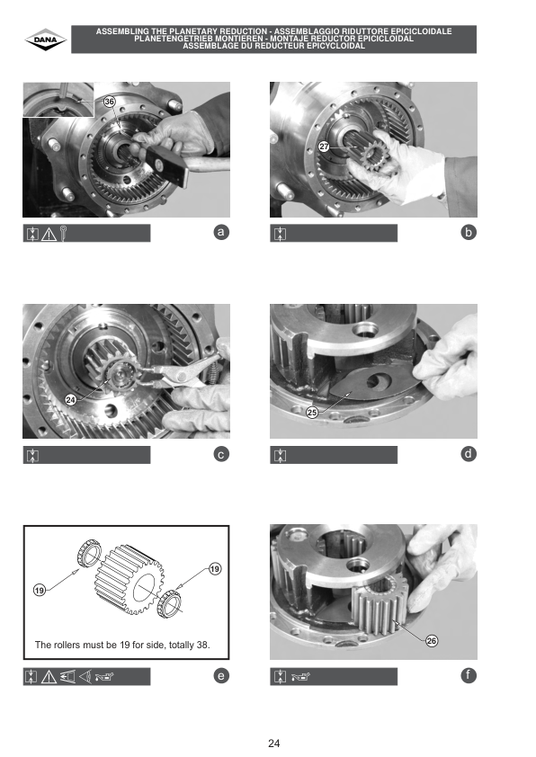
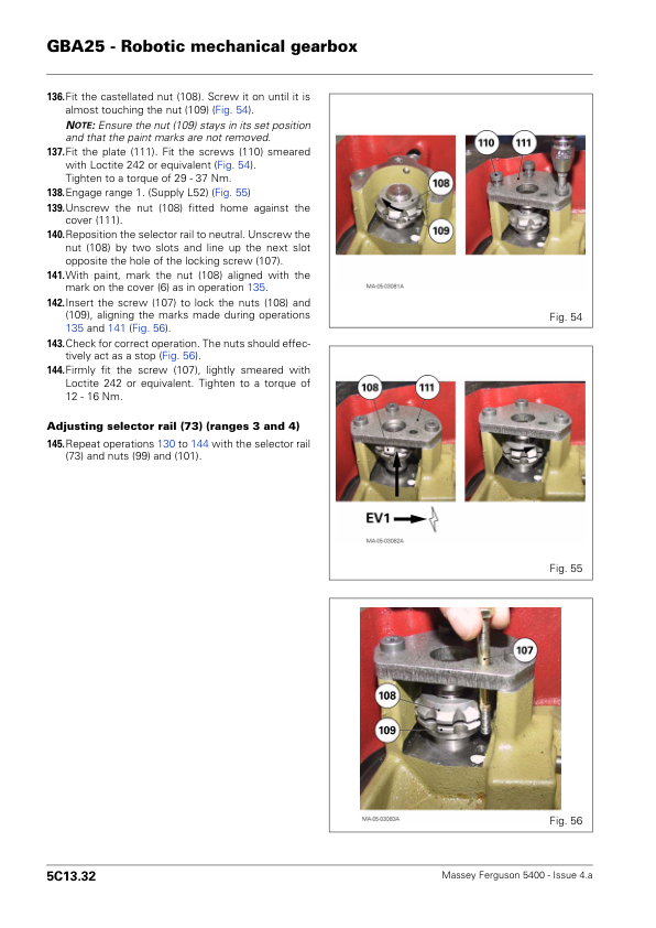
The gearbox material distinguishes Power Shuttle, Powershift, robotic mechanical and super creeper arrangements, while the front axle chapters cover DANA 720, 725, 730 and 735 units, including fixed and suspended versions where specified. Match the relevant assembly to the tractor before consulting its diagrams, measurements or service procedures.
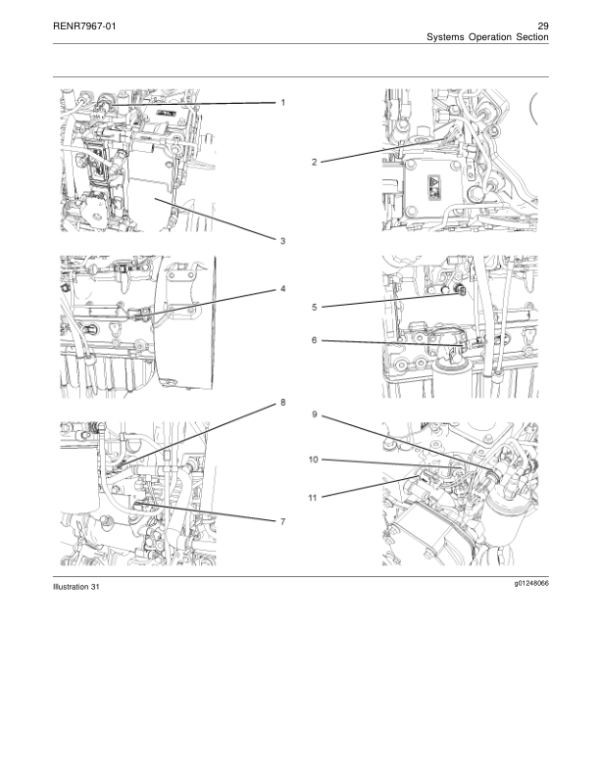
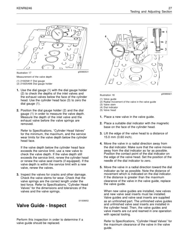
Engine chapters distinguish Sisu Tier 3 from Perkins 1104D mechanical and electronic configurations. Separate PTO sections cover two-speed and three-speed rear electrohydraulic systems, rear clutch assemblies and a Zuidberg front PTO. Consult the appropriate configuration-specific material when investigating faults or carrying out adjustments.




























1 review for Massey Ferguson 5425, 5435, 5445, 5460, 5465, 5470, 5475, 5480 Tractors Workshop Service Manual
There are no reviews yet.