Overview
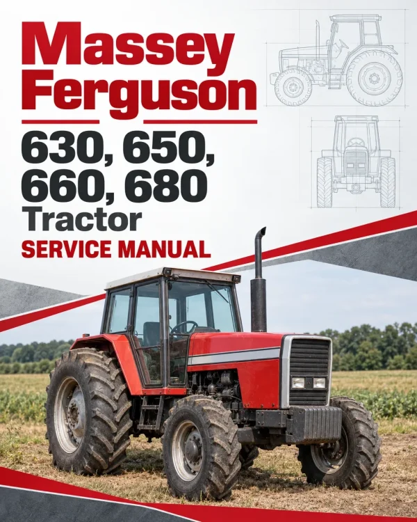
The Massey Ferguson 630, 650, 660 and 680 Tractor Workshop Service Repair Manual provides comprehensive technical information for servicing, maintaining, diagnosing and repairing these Massey Ferguson agricultural tractors. The workshop documentation covers Perkins diesel engines, clutch assemblies, mechanical transmissions, Carraro and ZF four-wheel-drive front axles, rear axle components, hydraulic lift systems, power take-off equipment, electrical systems, hydraulic steering and cab equipment.
Technical coverage includes Perkins engine specifications and adjustments, dual-stage and split-torque clutch servicing, Eaton 12×4 constant-mesh and synchromesh transmissions, ZF T3500 12×5 gearbox repairs, Ferguson hydraulic lift pump overhaul and Boschtronic electronic linkage diagnostics. Additional references include Carraro front axle differential servicing, Danfoss hydrostatic steering, hydraulic pressure testing, Prestolite starter and alternator repairs, air-conditioning maintenance, wiring diagrams and specialist workshop procedures.
Important Information: This workshop manual contains different front axle, transmission, clutch and hydraulic configurations. Separate sections identify Carraro CA 20.18, 20.21 and 20.29 front axles, ZF APL 345, 350 and 359 front axles, Eaton 12×4 transmissions, the ZF T3500 gearbox, and Ferguson, Hydrotronic and Boschtronic hydraulic lift systems. Confirm the tractor model and installed components before selecting the applicable technical procedures.
Table of Contents
Massey Ferguson 630, 650, 660, 680 Manual
-
01. Introduction and Workshop Safety
- Introduction to the Workshop Service Manual
- Using the Service Manual
- Recording Manual Changes and Updates
- General Workshop Safety
- Correct Workshop Servicing Techniques
- Fundamentals of Technical Measurement
- Workshop Measuring Instruments
- Practical Measurement Examples
- General Measurement Principles
- Recommended Bolt Tightening Torques
- Technical Units of Measurement
- Measurement Conversion Tables
- Imperial and SI Unit Equivalents
- Technical Unit Prefixes
- Loctite Workshop Products
- AGCO Environmental Policy
- Battery Recycling Requirements
-
02. Splitting the Tractor
- Tractor Separation General Information
- Separating the Engine and Front Axle
- Engine and Front Axle Reassembly
- Separating the Engine and Gearbox
- Engine and Gearbox Reassembly
- Engine and Gearbox Retaining Bolt Torques
- Separating the Gearbox and Rear Axle
- Gearbox and Rear Axle Reassembly
- Rearward Tractor Separation Between Gearbox and Rear Assembly
- Front Hood Sheet Metal Removal
- 03. Reserved
-
04. Carraro 4WD Front Axle – CA 20.18, 20.21 and 20.29
- Carraro Four-Wheel-Drive Front Axle General Information
- Carraro Front Axle Technical Specifications
- Front Axle Final Drive Component Identification
- Front Final Drive Disassembly
- Front Final Drive Reassembly and Adjustment
- Front Final Drive Pivot Assemblies
- Pivot Assembly Disassembly and Reassembly
- Front Axle Half-Shaft Universal Joints
- Half-Shaft Spider Disassembly and Reassembly
- Front Axle Trumpet and Pivot Bushings
- Bushing and Retainer Removal
- Front Axle Bushing and Retainer Inspection
- Bushing and Retainer Installation
- Front Axle Pinion and Differential Assembly
- Front Axle Removal
- Differential Removal and Disassembly
- Drive Pinion Disassembly
- Differential and Pinion Inspection
- Pinion Reassembly and Adjustment
- Front Differential Reassembly
- Final Pinion and Differential Adjustments
- Front Driving Box and Bearing Shell
- Driving Box Component Identification
- Driving Box Disassembly and Inspection
- Driving Box Reassembly and Adjustment
- Front Bearing Shell and Step-Up Gearbox Bearings
- Front Axle Steering Cylinder
- Steering Cylinder Disassembly
- Steering Cylinder Component Inspection
- Steering Cylinder Reassembly
- Front Axle Component Tightening Torques
- 05. ZF 4WD Front Axle – APL 345, 350 and 359
-
06. Perkins Diesel Engines
- Engine Valve Tip Clearance Adjustment
- Fuel Injector Nozzle Inspection
- Fuel Injector Atomisation and Pressure Testing
- Fuel Injector Nozzle Sealing Test
- Fuel Injector Atomisation and Noise Testing
- Diesel Fuel Injection Timing Adjustment
- Engine Cylinder Compression Testing
- Perkins P4000 Engine Specifications
- Perkins 1000 Series Engine Specifications
- Perkins 1000 Series Engine Cooling System
- Engine Workshop Service Specifications
- Engine Cylinder Block Specifications
- Cylinder Sleeve and Piston Specifications
- Piston Ring and Ring End Clearance Specifications
- Connecting Rod and Connecting Rod Bushing Specifications
- Crankshaft and Thrust Washer Specifications
- Camshaft and Valve Control Shaft Specifications
- Cylinder Head Service Specifications
- Intake and Exhaust Valve Specifications
- Valve Guide and Valve Spring Specifications
- Tappet and Rocker Arm Specifications
- Engine Timing Gear Specifications
- Injection Pump Drive Gear Specifications
- Engine Oil Pressure Relief Valve Specifications
- Turbocharger Specifications
- Diesel Injection Pump Specifications
- Engine Component Tightening Torques
-
07. Clutches and Flywheel Assemblies
- Clutch Configurations for Advanced 600 Series Tractors
- Clutches and Flywheels for 600 Series Tractors
- General Clutch Service Information
- Common Causes of Clutch Overheating
- Clutch Removal and Refitting Precautions
- Dual-Stage Clutch Component Identification
- Split-Torque Clutch Component Identification
- Clutch Removal and Disassembly
- Dual-Stage Clutch Disassembly
- Split-Torque Clutch Disassembly
- Clutch Component Inspection
- Clutch Pressure Plate Machining and Skimming
- Intermediate Flywheel Machining and Skimming
- Heavy-Duty Split-Torque Clutch
- Heavy-Duty Single-Stage Clutch with Cerametallic Disc
- Dual-Stage Clutch Reassembly
- Split-Torque Clutch Reassembly
- Engine Flywheel Machining and Skimming
- Flywheel Ring Gear
- Engine Flywheel Refitting and Alignment
- Clutch Refitting to Flywheel
- Clutch Release Lever Adjustment
- Clutch Pedal Free Travel Adjustment
- Second-Stage Clutch Engagement Adjustment
- Clutch Troubleshooting
- Double-Disc Clutch Component Identification
- Double-Disc Clutch Disassembly
- Double-Disc Clutch Component Inspection
- Double-Disc Clutch Component Machining
- Double-Disc Clutch Assembly
- Flywheel Reassembly and Adjustment
- 08. Eaton Constant-Mesh 12×4 Gearbox
-
09. Eaton Synchromesh 12×4 Gearbox
- Eaton 12×4 Synchromesh Gearbox Introduction
- Gearbox Component Identification
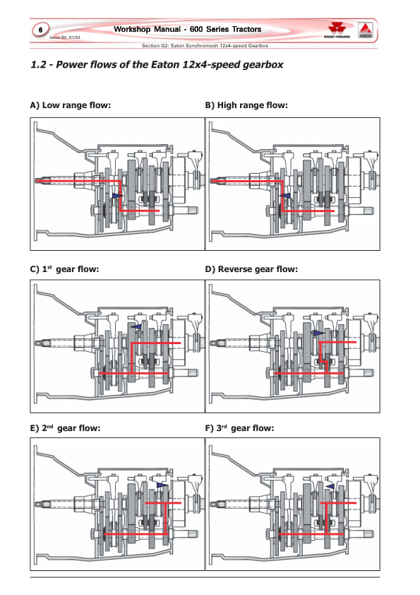
- Transmission Power Flow Diagrams
- Gearbox Gear Arrangement Diagrams
- Gearbox Removal from Tractor
- Gearbox Installation on Workshop Support
- Clutch Release Mechanism
- Clutch Release Mechanism Disassembly and Inspection
- Clutch Release Mechanism Reassembly
- Slow and Fast Range Assembly
- High and Low Range Component Identification
- Range Assembly Removal and Disassembly
- Slow/Fast Range Reassembly
- Front Input Housing and Input Shafts
- Input Housing Removal and Disassembly
- Input Housing Reassembly
- High and Low Range Axial Play Adjustment
- Main Transmission Output Shaft
- Mainshaft Removal and Disassembly
- Mainshaft Reassembly and Adjustment
- PTO Output Shaft and Lower Layshaft
- PTO Shaft Removal and Disassembly
- Transmission Layshaft Removal
- Lower Layshaft Reassembly
- Lower Range Axial Play Adjustment
- PTO Output Shaft Reassembly
- Reverse Gear Assembly
- Reverse Gear Removal and Disassembly
- Reverse Gear Reassembly
- Transmission Synchroniser Assemblies
- Synchroniser Component Identification
- Synchroniser Reassembly
- Selector Fork Centralisation
- Gearbox Component Inspection
- Gearbox Failure Diagnosis and Troubleshooting
- Transmission Bushings and Sleeve Service Recommendations
-
10. ZF T3500 12×5 Gearbox
- ZF T3500 Gearbox General Description
- Gearbox Component Identification
- Transmission Gear Tooth Specifications
- Gearbox Power Flow Diagrams
- ZF T3500 Gearbox Lubrication System
- Gear and Final Drive Arrangement Diagrams
- Neutral Starting Switch
- Gearbox Maintenance Recommendations
- Gearbox Removal from Tractor
- Gearbox Installation on Service Support
- Gear Shift Levers and Upper Cover
- Gear Shift Lever Shafts and Forks
- Gear Selector Shaft Reassembly and Adjustment
- Transmission Lubrication Circuit
- Gearbox Lubrication Components
- Lubrication System Removal and Disassembly
- Oil Pressure Maintaining Valve Test
- Hydraulic Pump Drive Box
- Hydraulic Pump Drive Component Identification
- Hydraulic Pump Drive Removal and Disassembly
- Hydraulic Pump Drive Inspection and Reassembly
- Clutch Engagement Mechanism
- Clutch Engagement Assembly Removal
- Clutch Engagement Component Inspection
- Clutch Engagement Mechanism Reassembly
- Four-Wheel-Drive Drop Box
- 4WD Drop Box Component Identification
- Four-Wheel-Drive Drop Box Removal and Disassembly
- 4WD Drop Box Inspection and Reassembly
- Four-Wheel-Drive Coupling Adjustment
- Drop Box Installation into Gearbox
- Gearbox Internal Component Disassembly
- Upper Front Transmission Shaft
- Transmission Input Shaft
- Reverse Gear Assembly
- PTO Input Shaft
- PTO Output Shaft
- PTO Intermediate Shaft
- Rear Upper Transmission Shaft
- Transmission Output Shaft
- Four-Wheel-Drive Intermediate Assembly
- Gear Synchronising Assemblies
- Gearbox Component Inspection
- Gearbox Noise Troubleshooting
- Difficulty Engaging Transmission Gears
- Transmission Gears Slipping Out
- Gearbox Reassembly and Adjustment
- Four-Wheel-Drive Intermediate Shaft Reassembly
- Transmission Output Shaft Reassembly
- Rear Upper Shaft Reassembly
- 540/1000 RPM PTO Drive Assembly
- PTO Input and Output Shaft Reassembly
- Reverse Gear Reassembly
- Transmission Input Shaft Reassembly
- Upper Front Shaft Reassembly
- Final Gearbox Assembly
- 11. Rear Axle
-
12. Ferguson Hydraulic Lift System
- Ferguson Hydraulic Lift System General Information
- Hydraulic System Component Identification
- Ferguson Hydraulic Linkage Operating Principles
- Hydraulic Pump Check Valve Positioning
- Hydraulic Draft Control System
- Hydraulic Position Control System
- Hydraulic System Flow Diagram
- Ferguson Hydraulic Lift Pump
- Hydraulic Lift Pump Removal and Disassembly
- Hydraulic Pump Component Inspection
- Suction and Outlet Valve Seat Machining
- Hydraulic Pump Reassembly
- Hydraulic Pump Adjustment and Refitting
- Hydraulic Lift Cover Removal
- Hydraulic Lift Cover Disassembly
- Hydraulic Lift Cover Component Inspection
- Hydraulic Lift Cover Reassembly
- Hydraulic Lift Internal Adjustments
- Hydraulic Lift Cover Refitting
- Hydraulic Lift External Adjustment
- External Hydraulic Lift Cylinders – MF 630 and 650
- External Hydraulic Lift Cylinders – MF 660 and 680
- 13. Hydrotronic Hydraulic Lift System
-
14. Boschtronic Hydraulic Lift System
- Boschtronic Hydraulic Lift Operating Principles
- Boschtronic System Component Identification
- Electronic Hydraulic Lift Control Panel
- Control Panel Component Identification
- Boschtronic System Resetting
- Boschtronic Hydraulic Circuit Diagrams
- Boschtronic Electrical Circuit Diagrams
- Hydraulic Lift Control Valve
- Boschtronic Raising and Lowering Valve Circuit
- Hydraulic Lift Control Valve Overhaul
- Hydraulic Lift Sensor Installation
- Hydraulic Position Sensor Adjustment
- Hydraulic Draft Sensor Installation
- Electronic Control Panel Maintenance
- Boschtronic Control Unit and Wiring Harness
- Electrical Connector Maintenance Precautions
- Boschtronic Electronic Troubleshooting
- Hydraulic Position Sensor Testing
- Hydraulic Draft Sensor Testing
- Boschtronic Fault Diagnosis
- Boschtronic Technical Specifications
- 15. Power Take-Off – Live and Independent
-
16. Electrical System
- Electrical System General Information
- Electrical System Specifications
- Electrical Circuit Diagrams for Platform Tractors
- Electrical Circuit Diagrams for Cab Tractors
- Electrical Board, Fuses, Relays and Diodes
- Fuse Identification
- Cab Electrical Relay Identification
- Prestolite Alternator
- Alternator Disassembly
- Alternator Reassembly
- Alternator Testing
- Prestolite Starter Motor
- Starter Motor Disassembly
- Starter Motor Component Cleaning and Inspection
- Starter Motor Reassembly
- Starter Motor Performance Testing
- Instrument Panel Disassembly
- Instrument Panel Reassembly
- Electrical Relay Components
- Fuel Level Sensor
- Engine Temperature Sensor
- Fuel Injection Pump Solenoid
- Tractor Battery
-
17. Auxiliary Hydraulic and Steering Systems
- Auxiliary Hydraulic System Introduction
- Auxiliary Hydraulic Circuit Diagrams
- Hydraulic System Testing
- Hydrostatic Steering Hydraulic Testing
- Auxiliary Hydraulic Control Valve Pressure Testing
- Danfoss Hydrostatic Steering Unit
- Danfoss Steering Unit Oil Flow
- Danfoss OSPC LS Closed-Centre Steering Circuit
- Hydrostatic Steering Component Identification
- Hydrostatic Steering Hydraulic Connections
- Danfoss Steering Unit Overhaul Recommendations
- Hydrostatic Steering Unit Disassembly and Inspection
- Danfoss Steering Unit Reassembly
- Danfoss Hydraulic Priority Valve
- Auxiliary Hydraulic Control Valve
- Non-Variable Flow Hydraulic Control Valve
- Variable-Flow Hydraulic Control Valve
- Auxiliary Hydraulic Pump Component Identification
- Hydraulic Pump Removal and Disassembly
- Hydraulic Pump Inspection and Troubleshooting
- Hydraulic Pump Reassembly
- Hydraulic Oil Filtration
- Hydraulic Heat Exchanger
-
18. Cab, Air Conditioning and Heating
- Cab Air Conditioning System Introduction
- Air Conditioning Refrigeration Principles
- Air Conditioning Cooling Cycle
- Air Conditioning System Operation
- Air Conditioning Technical Specifications
- Air Conditioning Safety Recommendations
- Air Conditioning General Maintenance
- Air Conditioning Preventive Maintenance
- Air Conditioning Electrical Diagram
- Air Conditioning Refrigerant Servicing
- Air Conditioning Circuit Draining
- Air Conditioning Leak Detection
- System Evacuation and Vacuum Generation
- Air Conditioning System Refrigerant Refilling
- Air Conditioning Pressure Testing
- Air Conditioning Service Tools
- Air Conditioning System Troubleshooting
- Air Conditioning Compressor Troubleshooting
- Front Windscreen Wiper
- Cab Fan and Heating System
- 19. Tractor General Basic Specifications
Front Axle and Drive Box Identification
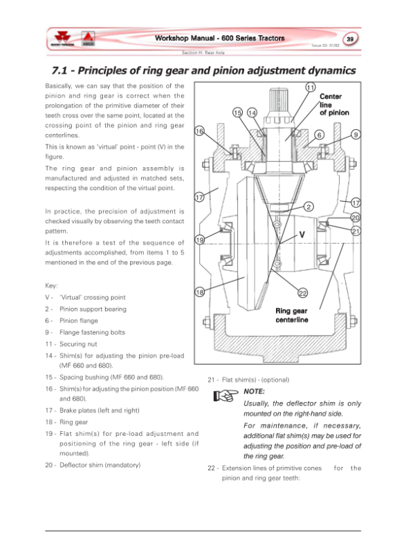
The front axle documentation distinguishes Carraro CA 20.18, CA 20.21 and CA 20.29 arrangements from ZF APL 345, APL 350 and APL 359 systems. The Carraro section includes final drive repairs, differential and pinion adjustments, pivot components, steering cylinder servicing and driving box procedures. Select the axle-specific reference that matches the tractor being serviced.
The gearbox documentation also separates Eaton constant-mesh and synchromesh 12×4 transmissions from the ZF T3500 12×5 gearbox. The original reference notes that the primary drive box on certain MF 630 and MF 650 configurations is covered under section G3, corresponding to the ZF T3500 gearbox chapter.

















Reviews
There are no reviews yet.