Overview
The Kubota KC250H and KC250HR Dumper Workshop Service Manual provides technical documentation for maintenance, troubleshooting, inspection, adjustment and component servicing of these Kubota tracked dumpers. The workshop reference covers machine identification, service specifications, safety covers, engine removal, driveline and chassis components, steering controls, vessel mechanisms, electrical equipment and hydraulic systems. It supports technicians in diagnosing operating problems, inspecting undercarriage assemblies, adjusting steering and hydrostatic transmission components, and performing applicable maintenance and repair procedures.
The documentation includes rubber track tension adjustment, idler and roller inspection, steering neutrality and linearity adjustments, hydraulic pressure settings and hydrostatic transmission (HST) operation. Separate hydraulic circuit diagrams cover One-Way Dump and Turn & Dump configurations, while the electrical section addresses switches, relays, indicators and operational checks. Additional technical references include control operating forces, hydraulic cylinder speeds, falling rates, tightening torques, replacement consumables and troubleshooting procedures for starting, travelling and steering faults.
Notice: The workshop documentation includes separate hydraulic circuit diagrams for One-Way Dump and Turn & Dump configurations. Confirm the installed dumping equipment before applying hydraulic diagrams or adjustment procedures. The supplied chapter index does not explicitly establish which configuration corresponds to each model designation.
Table of Contents
Kubota KC250H, KC250HR Manual
-
01. Introduction
- Purpose of the Workshop Service Manual
- Manual Organisation and Composition
- Important Notices to Service Technicians
-
02. Service Data and Technical Specifications
- Machine Component Names and Functions
- Product Technical Specifications
- Tool Bag Contents
- Control Lever Stroke and Operating Force
- Hydraulic Cylinder Operating Speed
- Hydraulic Cylinder Falling Rate
- Machine Serial Number Location
- Product Model and Production Number Identification
- Engine Model Number Identification
- Standard Hex-Head Bolt and Nut Tightening Torques
- Flange Bolt and Nut Tightening Torques
- Hydraulic Hose Joint Tightening Specifications
- Specific Component Fastening Requirements
- Fuel, Lubricant and Cooling Water Specifications
- Consumables and Replacement Parts Reference
-
03. Safety Covers
- Safety Cover Removal Procedures
-
04. Engine
- Engine Removal Procedures
-
05. Driveline, Chassis and Rubber Tracks
- Driveline Mechanism
- Chassis Mechanism
- Component Parts Diagrams
- Undercarriage Assembly and Adjustment References
- Track Idler Construction and Assembly
- Roller A — Mobile Track Roller
- Roller B — Fixed Track Roller
- Upper Roller — Carrier Roller
- Rubber Track Tension Adjuster
- Track Tension Adjustment Procedures
- Rubber Track Construction and Maintenance
- Track Idler Maintenance Standards
- Mobile and Fixed Roller Maintenance Standards
- Upper Carrier Roller Maintenance Standards
- Drive Sprocket Maintenance Standards
- Rubber Track Inspection and Service Standards
-
06. Steering System
- Steering System Diagram
- Steering System Adjustment
- Steering Neutrality Adjustment
- Steering Linearity Adjustment
-
07. Vessel and Dumping Mechanism
- Vessel Tailgate Closing Mechanism
-
08. Electrical Equipment
- Electrical Wiring Diagram
- Electrical Component Mechanisms and Functions
- Indicator System Inspection
- Fuel Level Sensor
- Ignition Switch
- Parking Brake Switch
- High/Low Travel Speed Switch
- Lighting Switch
- Horn Switch
- Electrical Relays
- Electrical Equipment Maintenance References
- Electrical Operational Confirmation Procedures
-
09. Hydraulic Equipment and Hydrostatic Transmission
- Hydraulic Circuit Diagram — One-Way Dump Configuration
- Hydraulic Circuit Diagram — Turn & Dump Configuration
- Hydraulic System Mechanisms and Functions
- Hydrostatic Transmission (HST) Pump
- HST Travelling Motor
- Hydraulic Control Valve
- Hydraulic Solenoid Valve
- Hydrostatic Transmission Circuit Maintenance Standards
- HST Hydraulic Pressure Setting Standards
- Hydrostatic Transmission Neutrality Adjustment
- Machine Towing Procedures
-
10. Troubleshooting and Fault Diagnosis
- Engine Does Not Start
- Machine Does Not Move with Travel Lever Engaged and Parking Brake Released
- Slow Travel Lever Response
- Unable to Perform Pivot Turn or Lock One Track
- Machine Does Not Travel Straight
- Unable to Turn to Either Side
- Fault Causes and Corrective Measures
Rubber Track Alignment, Steering Neutrality and HST Travel Diagnosis
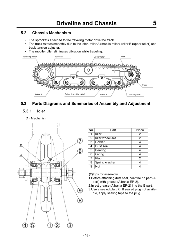
The Driveline and Chassis chapter provides component diagrams and maintenance standards for the idler, mobile and fixed rollers, upper carrier roller, drive sprocket and rubber tracks. It also includes specific guidance for track tension adjustment. When investigating abnormal track movement or undercarriage wear, these references help identify the relevant components and their inspection requirements. The Steering System chapter separately documents neutrality and linearity adjustments, which should be consulted when assessing straight-line travel or steering response.
The Hydraulic Equipment chapter covers the HST pump, travelling motor, control valve, solenoid valve and transmission pressure settings, together with a dedicated neutrality adjustment procedure. These references complement the Troubleshooting chapter, which identifies symptoms such as failure to travel, delayed lever response, inability to pivot-turn and difficulty maintaining straight-line movement. The manual also distinguishes One-Way Dump and Turn & Dump hydraulic circuits, making correct equipment identification important before inspecting hydraulic controls or performing adjustments.

























Reviews
There are no reviews yet.