Overview
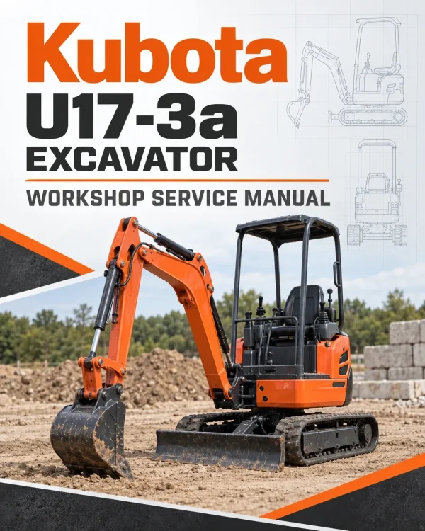
The Kubota U17-3a Excavator Workshop Service Manual provides technical documentation for maintenance, troubleshooting, inspection and component repair of this Kubota compact excavator. The workshop reference covers machine identification, undercarriage components, front attachments, engine systems, hydraulic pumps, control valves, swivel and travel motors, pilot controls and electrical equipment. Separate mechanism and servicing sections provide component construction, operating principles, technical specifications, diagnostic testing, disassembly and repair procedures.
The documentation includes regional maintenance requirements, engine accessory servicing, SM-E3B Series engine references, hydraulic pressure and flow testing, travel performance diagnosis and hydraulic component overhaul. The hydraulic chapters also address auxiliary service ports, unload valves, accumulators, the Two Pattern Selection System (TPSS) for applicable configurations and hydraulic hose routing. Electrical coverage includes the Kubota Intelligent Control System (KICS), digital meter functions, automatic idling, service-mode diagnostics, wiring circuits and anti-theft system troubleshooting.
Notice: The workshop documentation distinguishes EU, PP and KTA regional configurations, including separate maintenance references. The TPSS hydraulic control arrangement is specifically identified for the PP version. Confirm the machine configuration before selecting maintenance schedules, hydraulic procedures or electrical servicing information.
Table of Contents
Kubota U17-3a Manual
-
01. General Information, Safety and Maintenance
- Machine Body and Engine Identification Marks
- Safety Precautions Before Starting Service Work
- Safety Measures During Maintenance and Repair
- Preparation for Component Disassembly
- Disassembly and Reassembly Precautions
- Important Safety and Critical Functional Processes
- Inspection Requirements After Reassembly
- Hydraulic Piping Inspection
- Maintenance Intervals — EU Version
- Maintenance Intervals — PP (KTC/KCL) Version
- Maintenance Intervals — KTA Version
- Hydraulic Oil Checks for Machines Equipped with Breakers
- Scheduled Maintenance Items
- Operator-Oriented Troubleshooting References
- Periodic Replacement of Important Components
- Recommended Engine and Hydraulic Oils
- Excavator Lifting Capacity
- Machine Development and Product Information
- Minor-Change Technical Features
- Equipment Specification Comparisons
-
02. Machine Body — Mechanism and Servicing
- Major Machine Dimensions and Working Range
- Working Range with Rubber Crawlers
- Machine Technical Specifications
- Comparison with Earlier U17 and U17-3 Configurations
- Machine Body Structure and Function
- Overall Component Arrangement
- Undercarriage Construction and Components
- Machine Weight and Service Specifications
- Operating Lever Stroke and Operating Force
- Component Dimensions and Quality Specifications
- Front Attachment Pin, Bushing and Shim Installation
- Front Attachment Bushing Press-Fitting
- Front Attachment Greasing Points
- Upper Structure and Swivel Bearing
- Travel Operating Lever Assembly
- Engine Accelerator Lever
- Dozer Blade Operating Lever
- Boom Swing Pedal
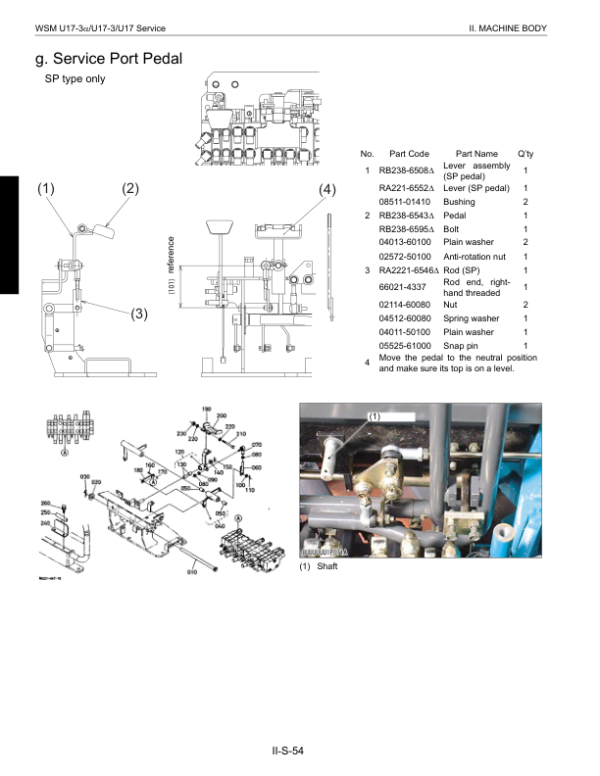
- Auxiliary Service Port Pedal
- Pilot Control Valve Installation
- Limit Switch Installation
- Operator Seat and Seat Belt
- Wrist Rest and Operator Canopy
- Machine Counterweight
- Undercarriage Track Tension Device
- Track Roller Inspection and Servicing
-
03. Engine — Mechanism and Servicing
- Engine Technical Specifications
- New Emissions-Control Engine Information
- Engine Configurations Associated with Minor Changes
- Engine Mounting Components
- Engine Air Cleaner
- Engine Radiator Assembly
- Thermostat Components
- Engine Muffler
- Hydraulic Pump Coupling
- Fuel Tank Components
- Engine Fuel Hoses
- Engine Component Arrangement
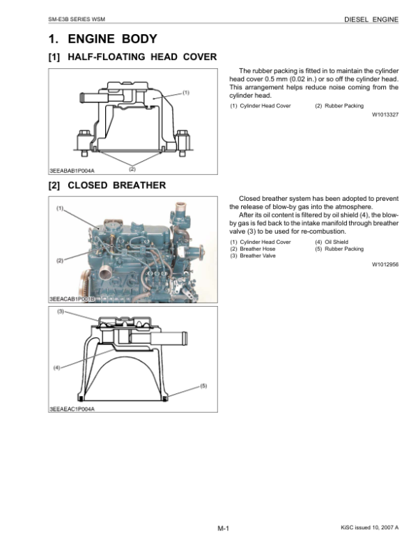
- SM-E3B Series Engine Workshop Reference
-
04. Hydraulic System — Mechanism and Servicing
- Hydraulic System Construction and Operating Principles
- Main Hydraulic Pump Structure and Function
- Main Hydraulic Control Valve
- Swivel Motor Construction and Operation
- Travel Motor Construction and Operation
- Pilot Valve and Remote Control Valve
- Hydraulic Unload Valve
- Hydraulic Selector Valve
- Hydraulic Component Accessories
- Auxiliary Service Port System
- Two Pattern Selection System (TPSS) — PP Version
- Hydraulic Component Layout and Configuration Comparison
- Complete Hydraulic Circuit Diagram
- Common Hydraulic Circuit Troubleshooting
- Hydraulic System Fault Diagnosis
- Hydraulic Pump Troubleshooting
- Swivel and Travel Motor Troubleshooting
- Swivel Performance Diagnosis
- Travel Performance Diagnosis
- Hydraulic Testing Instruments and Special Tools
- Hydraulic Pump Flow Measurement
- Hydraulic Pressure Measurement
- Hydraulic Drain Flow Measurement
- Hydraulic Block Performance Testing
- Hydraulic Operating Speed Measurement
- Straight Travel Performance Testing
- Swivel System Diagnostic Procedures
- Travel System Diagnostic Procedures
- Hydraulic Cylinder Natural Fall Measurement
- Control Lever and Travel Lever Operating Force
- Operating Lever Stroke Measurement
- Hydraulic Pump Service Specifications
- Hydraulic Relief Valve Specifications
- Swivel Motor Performance Specifications
- Travel Motor Performance Specifications
- Hydraulic Cylinder Specifications
- Auxiliary Service Port Flow Specifications
- Motor Oil Drain Measurement References
- Hydraulic Pump Disassembly and Reassembly
- Main Control Valve Disassembly and Reassembly
- Pilot Control Valve Disassembly and Reassembly
- Swivel Motor Disassembly and Reassembly
- Hydraulic Rotary Joint Disassembly and Reassembly
- Travel Motor Disassembly and Reassembly
- Hydraulic Cylinder Disassembly and Reassembly
- Dozer and Track Change Valve Servicing
- Hydraulic Unload Valve Disassembly
- Hydraulic Accumulator Servicing
- Hydraulic Oil Tank Disassembly
- Third-Line Hydraulic Components
- TPSS Valve Disassembly — PP Version Only
- Hydraulic Hose Installation and Routing
-
05. Electrical System and Electronic Diagnostics
- Electrical System Features and Functions
- Kubota Intelligent Control System (KICS)
- Digital Meter Features and Functions
- Digital Meter Operating Modes
- KICS Service Mode Menus
- Automatic Idling (AI) Control System
- Electrical Component Functions
- KICS Failure Diagnosis
- Service Mode Diagnostic Flowcharts
- Electrical Component Layout
- Electrical Circuit Diagram
- Revised Electrical Wiring Diagram
- General Electrical Troubleshooting
- Engine Electrical Fault Diagnosis
- Instrument Panel Inspection with Key Switch ON
- Instrument Panel Inspection During Engine Starting
- Electrical Coupler and Connector Inspection
- Electrical Component Testing
- Fuse Inspection
- Electrical Wiring Harness Inspection
- Battery Inspection and Testing
- Electrical Measuring Instruments and Special Tools
- Wire Harness Installation and Clamping Precautions
- Main Wiring Harness Layout
- Wiring Behind the Engine
- Wiring Above the Engine
- Unload Switch and Horn Wiring
- Front Electrical Cable Routing
- High-Speed Travel Switch and Horn Connections
- Engine Compartment and Fuel Sensor Wiring
- Right-Hand Console Wiring Harness
- Fuse and Battery Maintenance Checks
- Horn Inspection
- Glow Relay Inspection
- Glow Plug Testing
- Unload Safety Switch Inspection
- High-Low Travel Switch Inspection
- Solenoid Valve Testing
- Electric Fuel Pump Inspection
- Fuel Sensor Testing
- Engine Stop Solenoid and Coil Commander
- Engine Water Temperature Gauge Inspection
- Engine Oil Pressure Switch
- Electrical Relay Inspection
- Canopy Light Installation — KTA Version
- Anti-Theft System Construction and Operation
- Anti-Theft System Troubleshooting
- Anti-Theft Display Indications
PP-Version Hydraulic Controls and Regional Service Differences
The hydraulic documentation identifies the Two Pattern Selection System as a PP-version feature, with separate references for its mechanism and valve disassembly. The service material also includes hydraulic pump flow testing, pressure measurements, motor drain checks, swivel performance diagnosis and straight-travel testing. These measurements help distinguish hydraulic performance problems from operating-control or component faults. When inspecting the pilot control system or selector valves, confirm whether the installed machine uses the documented PP-version arrangement before selecting the procedure.
Maintenance schedules are divided between EU, PP and KTA configurations, and the manual includes additional hydraulic oil checks for equipment using hydraulic breakers. The electrical documentation provides KICS service-mode functions, digital meter diagnostics and automatic idling controls, together with separate inspection procedures for sensors, relays and wiring. These regional and electronic distinctions should be considered when diagnosing a machine or comparing its servicing requirements with earlier excavator configurations. The accompanying operating manual remains a separate reference for normal machine operation and routine user instructions.

























Reviews
There are no reviews yet.