Overview
The Massey Ferguson FC23 Front Cut Mower Workshop Service Manual provides technical information for maintaining, inspecting, troubleshooting and repairing the Massey Ferguson FC23 front mower. The documentation covers major component disassembly, engine accessories, transmission and power take-off equipment, hydrostatic transmission, power steering, four-wheel-drive rear axle, hydraulic system, electrical accessories, service specifications and mower deck components.
Workshop procedures include radiator and air cleaner servicing, engine removal, PTO clutch inspection, transmission and brake repairs, hydrostatic pump and control valve servicing, steering system troubleshooting, rear axle disassembly, hydraulic pressure testing and electrical safety switch inspections. The manual also provides HST pedal and auto-cruise adjustments, mower lift linkage servicing, gauge wheel assembly, tightening torque specifications and general component installation precautions.
Safety: Review the manual’s safety precautions before carrying out maintenance or repairs. The introductory section includes general safety rules, roll-over protective structure (ROPS) information and seat belt instructions.
Notice: Special bolts are installed at certain locations and must not be interchanged with ordinary bolts. Tighten bolts and nuts to their specified torque using a torque wrench, following the applicable service standards and assembly instructions.
Table of Contents
Massey Ferguson FC23 Manual
-
01. Introduction and General Information
- Introduction and Dealer Information
- Replacement Parts Information
- Units of Measurement and Manual References
- Safety Precautions and Safety Alert Symbols
- Safety Signal Words and Signs
- General Safety Rules
- Roll-Over Protective Structure (ROPS)
- Seat Belt Operation and Personal Protection
- General Operational Safety
- Machine Specifications
- Exterior Views and Dimensions
- Periodic Inspection Table
- Fluid Filling Diagram
-
02. Disassembly of Major Components
- General Precautions for Component Separation and Installation
- Preparation Before Disassembly
- Roller and Ball Bearing Installation
- Oil Seal and O-Ring Installation
- Snap Rings and Spring Pins
- Cotter Pin Installation
- Nuts, Bolts and Special Fastener Identification
- Specified Tightening Torque Requirements
- Lubricating Grease Fittings After Installation
- Other Component Installation Precautions
- Mower Deck Removal
-
03. Engine Accessories and Cooling System
- Engine Service Manual Reference
- Radiator Specifications and Construction
- Radiator Removal
- Radiator Leak Inspection
- Radiator Blockage Inspection and Cleaning
- Radiator Core and Exterior Component Inspection
- Radiator Assembly
- Daily Coolant Level Inspection
- Coolant Replacement and Antifreeze Precautions
- Cooling System Troubleshooting
- Air Cleaner Construction and Removal
- Air Cleaner Paper Element Cleaning
- Air Cleaner Assembly Precautions
- Fuel System
- Engine Removal from Chassis
- Engine Specifications and Service Standards
- Major Fastener Tightening Torques
- Standard Bolt Tightening Torques
-
04. Transmission, PTO Clutch and Brakes
- Transmission and Related Components
- Power Train and Driveline Sectional Views
- Front Wheel Drive Mechanism
- Preparing Access to the Transmission
- Power Take-Off (PTO) Clutch Construction
- PTO Case Removal
- PTO Clutch Removal and Disassembly
- PTO Clutch Component Inspection
- Clutch Separator Plate Inspection
- PTO Brake Disc Inspection
- PTO Clutch Reassembly
- Transmission Components
- Brake Construction
- Brake Drum Disassembly
- Brake Component Inspection
- Brake Assembly Precautions
- Transmission Disassembly, Inspection and Reassembly
-
05. Hydrostatic Transmission (HST)
- Hydrostatic Transmission Major Components
- HST Operating Diagram
- Hydrostatic Transmission Operating Principles
- Variable Displacement Hydraulic Pump
- Low-Pressure Relief Valve and Suction Check Valve
- High-Pressure Relief Valve
- Neutral Valve and Check Valve
- Unloading Valve
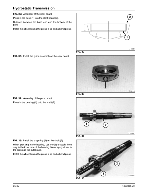
- Hydrostatic Transmission Disassembly and Assembly
- Required Service Tools and Press-In Jigs
- Disassembly Precautions
- Inspection and Wear Limits for HST Components
- Hydrostatic Transmission Reassembly
- HST Component Identification
- Hydrostatic Transmission Adjustments
- HST Pedal Adjustment
- HST Stopper Adjustment
- Brake Pedal and Auto-Cruise Lever Adjustment
- Drive Linkage Mechanism Setup
-
06. Power Steering System
- Power Steering System Construction
- Power Steering Operating Principles
- Steering System Operation in Neutral Position
- Steering System Operation During Steering
- Power Steering Disassembly
- Power Steering Reassembly
- Steering System Troubleshooting and Corrective Measures
-
07. Rear Axle – Four-Wheel Drive (4WD)
- Rear Axle Construction and Sectional Views
- Four-Wheel-Drive Rear Axle Disassembly
- Rear Axle Final Case and Related Components
- Final Case Component Inspection
- Rear Axle Reassembly Precautions
-
08. Hydraulic System
- Hydraulic System Circuit Diagrams
- Hydraulic Main Piping Layout
- Hydraulic System Specifications
- Hydraulic Component Construction and Inspection
- Hydraulic Oil Filter
- Stabilizer and Relief Valve
- Hydraulic Gear Pump
- Hydraulic Relief Valve Inspection
- Hydraulic Control Valve
- Hydraulic Valve Operation – Neutral Position
- Hydraulic Valve Operation – Lowering Position
- Hydraulic Valve Operation – Raising Position
- Hydraulic Valve Operation – PTO Disengaged
- Hydraulic Valve Operation – PTO Engaged
- Main Hydraulic Relief Pressure Testing
- Hydraulic System Troubleshooting
-
09. Electrical System and Accessories
- Electrical System Description and Specifications
- Electrical Component Identification
- Electric Fuel Pump
- Instrument Pilot Lamp Array
- Safety Switch Operation and Testing
- Electrical Wiring Diagrams
- Starter Switch Wiring Diagram
- Four-Wheel-Drive Steering Post Electrical Components
- Brake Switch
- Power Take-Off (PTO) Switch Assembly
-
10. Service Standards and Technical Data
- Service Standards and Component Specifications
- Fluid Filling Capacity Table
- Specified Bolt and Nut Tightening Torques
- Locking Bolts and Nuts
-
11. Mower Deck and Lift Linkage
- Mower Deck Technical Specifications
- Mower Lift Linkage
- Mower Lift Cylinder Linkage
- Lift Linkage Clearance Adjustment
- Mower Deck Gear Assemblies
- Gauge Wheel Assembly
- Mower Deck Troubleshooting
- 12. Index
Hydrostatic Drive and PTO Clutch Service References
The FC23 workshop documentation separates the conventional transmission components from the hydrostatic transmission system. The HST chapter includes variable pump operation, hydraulic relief and check valves, component wear limits, HST pedal adjustments, stopper settings and auto-cruise linkage adjustments. These references are distinct from the transmission chapter covering the PTO clutch, transmission components and brake drum.
The hydraulic section includes the control valve operating positions for raising, lowering and engaging or disengaging the PTO, along with main relief pressure testing. The mower deck chapter separately covers lift cylinder linkage, link clearance, mower gears and gauge wheel assembly. The service standards provide the specified tightening torques and fastener information required when reinstalling components.




























Reviews
There are no reviews yet.