Overview
Maintenance and repair information for this model is organized by system in the Volvo L50C Wheel Loader Service Repair Manual. Coverage includes engine systems, power transmission, braking equipment, and steering components.
The service topics include fuel injection timing references, hydraulic transmission controls, turbocharger components, working-hydraulics pumps, and lifting-frame and link-arm assemblies.
Table of Contents
Volvo L50C Manual
- 01. General
-
02. Standard Parts, Service
- Service — General, common info about 171 – 179
-
03. Engine with Mounting and Equipment
- General, engine installation and its function
- Engine — General, common info about 211 – 218
- Engine — Valve mechanism
- Lubricating System — General, common info about 221 – 224
- Fuel System — Fuel pump; filter; strainer
- Fuel System — Fuel tank; fuel filling pump
- Fuel System — Injection pump; regulator; pump companion
- Fuel System — Injector; delivery pipe
- Fuel System — Control system; control unit (for ex. injection timing adjuster)
- Inlet System; Exhaust System — Turbo charger
- Inlet System; Exhaust System — Air cleaner with connections; air pre-heater
- Inlet System; Exhaust System — Charge air cooler with connections
- Cooling System — General, common info about 261 – 269
- Cooling System — Coolant pump; thermostat
- Engine Control — Cold start control
-
04. Elec. System; Warning System; Information System; Instruments
- Comprehensive info, electrical system
- Battery; Energy Storage System; Mounting Parts — Battery
- Alternator; Charging; Electric Motor; Electric Drives — Alternator inclusive drive
- Starting System — Starter motor inclusive solenoid
- Lighting — Bulbs
- Lighting, front, including parking light and day running light
- Cable; Fuse; Relay — General, common info about 371 – 379 — Wiring diag. 22D. 4th hydr. fctn., 4th hydr. fctn., actvt. thru. brake press. chg. attachm. locking brake press. chrg. and attachm. lock
- Cable; Fuse; Relay — General, common info about 371 – 379 — Wiring diagram 5D. Preheating engine TD40KAE. W.e.fr. serial number 11233
- Cable; Fuse; Relay — General, common info about 371 – 379 — Wiring diagram 6B. Single lever ctrl. w. boom kick-out and bucket pos., floating position and max. flow via 3rd hydr function
- Cable; Fuse; Relay — General, common info about 371 – 379 — Wiring diagram 8. Pressure draining, brake pressure charging, attachment locking
- Cable; Fuse; Relay — General, common info about 371 – 379 — Wiring diagram 15C. Dual control Forward/Reverse during Limp-Home operation ECU
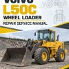
- Cable; Fuse; Relay — General, common info about 371 – 379 — Wiring diagram 19. Mechanical parking brake with Rider truck safety norm
- Cable; Fuse; Relay — General, common info about 371 – 379 — Wiring diagram 19D. Hydraulic parking brake with rider truck safety norm
- Cable; Fuse; Relay — General, common info about 371 – 379 — Wiring diagram 20B. Lever steering (CDC) w. adjust. ramp gen. Up to and incl. s/n: 10631
- Cable; Fuse; Relay — General, common info about 371 – 379 — Wiring diagram 20B. Lever steering (CDC) w. non-adjust ramp gen. W.e.fr. s/n: 10632
- Cable; Fuse; Relay — General, common info about 371 – 379 — Wiring diagram 21D. 4th hydraulic function, activation through brake pressure charging
- Cable; Fuse; Relay — General, common info about 371 – 379 — Wiring diagram 22. 4th hydraulic function, activation with LS-signal and attachment locking
- Cable; Fuse; Relay — Electrical distribution box; fuse box; junction box
- Instrument; Sensor; Warning and Information System — General, common info about 383 – 387
- Instrument; Sensor; Warning and Information System — Warning/information unit, display unit
-
05. Power Transmission
- General, common info about 410 – 436
- Transmission, hydraulic control
- Hydrostatic Drive — General, common info about 441 – 443
- Front Axle; Rear Axle — General, common info about 461 – 468
- Miscellaneous — General, common info about 491 – 492
-
06. Brake
- Comprehensive info about brakes
- Wheel Brake — Front wheel brake (wet brake)
- Hydraulic Brake System — General, common info about 520 – 522
- Hydraulic Brake System — Brake valve
- Parking Brake — General, common info about 551 – 554
-
07. Steering
- Comprehensive info, steering
- Steering — General, common info about 641 – 647
- Steering — Hydraulic equipment
- Lever Steering
-
08. Frame; Springs; Damping; Axle Suspension; Wheel/track Unit
- Frame — General, common info about 711 – 718
- Frame Link — Bearings
- Axle Suspension — Pivot suspension
-
09. Machinery House; Cab; Exterior Trim Parts Anywhere
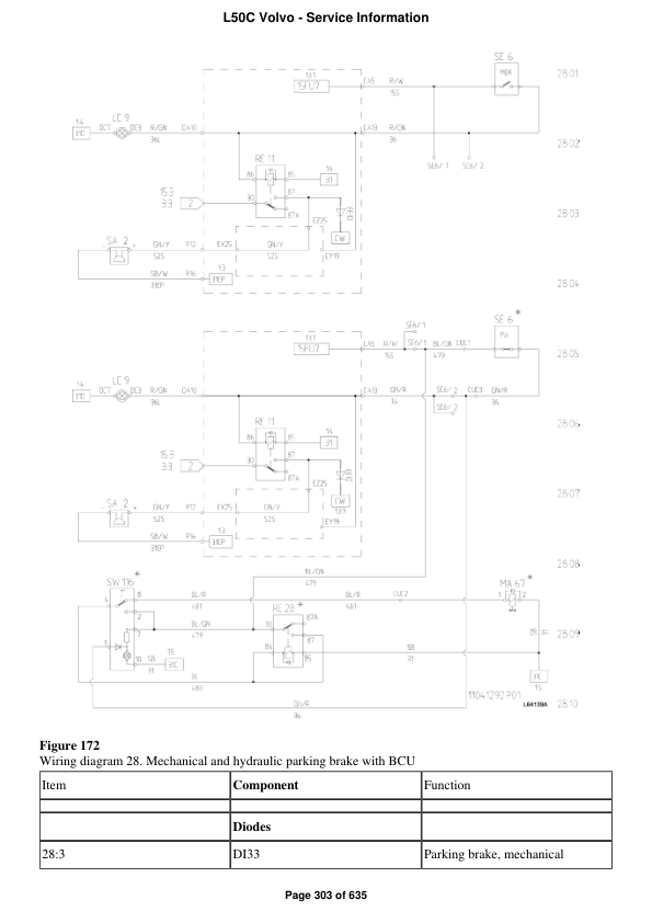
- Air Conditioning Unit — General, common info about 872 – 877
- Air Conditioning Unit — Cooling unit
-
10. Hydraulic System; Digging/ Handling/ Grading Equipm.; Misc. Equip.
- Working Hydraulics; Servo Hydraulics — General, common info about 911 – 917 — Hydraulic diagram basic machine, 3rd/4th, floating function s/n 10006-10852
- Working Hydraulics; Servo Hydraulics — General, common info about 911 – 917 — Hydraulic diagram basic machine, 3rd/4th, floating function w.e.fr. s/n 10853
- Working Hydraulics; Servo Hydraulics — Working hydraulics
- Working Hydraulics; Servo Hydraulics — Pump, working hydraulics
- Working Hydraulics; Servo Hydraulics — Servo hydraulic system
- Working Hydraulics; Servo Hydraulics — Other hydraulic equipment — 5th/6th hydraulic functions and attachment hydraulics GP, hydraulic diagram
- Working Hydraulics; Servo Hydraulics — Other hydraulic equipment — Accumulator, Boom Suspension System, precharging pressure checking and adjusting
- Unit, Load Handling — Lifting frame work with mounting and link arm system
Serial-Number Qualifiers in Service Diagrams
Use the entries “Wiring diagram 20B. Lever steering (CDC) w. adjust. ramp gen. Up to and incl. s/n: 10631” and “Hydraulic diagram basic machine, 3rd/4th, floating function w.e.fr. s/n 10853” to locate the named component information.
The serial qualifiers apply to those named entries, not automatically to every section of the manual. Keep each range attached to its diagram or component reference.



























Reviews
There are no reviews yet.