Overview
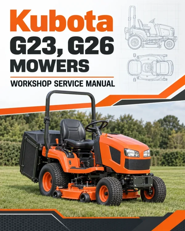
The Kubota G23 and G26 Mower Workshop Service Manual provides technical documentation for maintenance, troubleshooting, inspection and component repair of these Kubota riding mowers. The workshop reference covers diesel engine systems, hydrostatic transmission (HST), transaxle, mechanical and hydraulic power take-off (PTO) clutches, front axle, power steering, hydraulic equipment, electrical systems, mower assemblies and grass-collector mechanisms. Its technical sections provide component construction, operating principles, service specifications, checking, adjustment, disassembly and repair procedures.
The documentation includes separate engine specifications, transaxle and PTO clutch servicing, hydraulic steering circuits, mower lifting mechanisms and grass-collector hydraulic controls. Hydraulic coverage distinguishes low-dump (LD) and high-dump (HD) configurations, including dump cylinders and collector lifting components, while electrical references address starting, charging, safety switches, collector duct sensors and warning buzzers. Dedicated Mower and Grass Collector chapters provide additional inspection and repair procedures, supported by maintenance schedules, lubrication requirements, tightening torques and special service tools.
Notice: The workshop documentation distinguishes mechanical PTO clutch arrangements associated with G23 configurations from hydraulic PTO clutch arrangements associated with G26 configurations. Separate hydraulic circuits are also provided for LD and HD grass-collector systems. Confirm the installed PTO and collector configuration before selecting component specifications, hydraulic circuits or servicing procedures.
Table of Contents
Kubota G23, G26 Manual
-
01. Information and Safety
- Safety First and Workshop Safety Instructions
- Mower Safety Decals and Warning Labels
- Machine Technical Specifications
- Machine Dimensions
-
02. General Information and Maintenance
- Machine Identification
- Machine Serial Number Identification
- Engine Cylinder Number Identification
- General Workshop Precautions
- Electrical Wiring Handling Precautions
- Battery, Fuse and Electrical Connector Precautions
- Circuit Tester Handling Instructions
- Electrical Wiring Colour Identification
- Lubricants, Fuel and Coolant Requirements
- General Fastener Tightening Torques
- Stud Bolt Tightening Specifications
- UNC and UNF Threaded Fastener Specifications
- Plug Tightening Torques
- Machine Maintenance Checklist
- Daily Walk-Around Inspection
- Daily Mower Inspection
- Operator Seat Inspection Checks
- Key Switch and Starting-System Daily Checks
- Initial 50-Hour Maintenance
- Periodic Maintenance — Every 50 Hours
- Periodic Maintenance — Every 100 Hours
- Periodic Maintenance — Every 150 Hours
- Periodic Maintenance — Every 200 Hours
- Periodic Maintenance — Every 400 Hours
- 1,500-Hour Maintenance Checks
- 3,000-Hour Maintenance Checks
- Annual and Two-Year Maintenance Requirements
- Additional Maintenance and Service Checks
- Special Service Tools for Engine Repair
- Special Service Tools for Machine Components
- Tyre Inflation Pressure
- Wheel Inspection
- Implement Limitations
-
03. Engine — Inspection and Servicing
- Engine Troubleshooting
- Engine Servicing Specifications — G23
- Engine Servicing Specifications — G26
- Engine Tightening Torque Specifications
- Engine Body Checking and Adjustment
- Engine Lubricating System Inspection
- Cooling System Checking and Adjustment
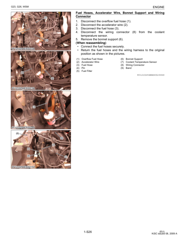
- Engine Fuel System Checking and Adjustment
- Engine Separation and Removal
- External Engine Component Removal
- Cylinder Head and Valve Disassembly
- Gear Case and Timing Gear Disassembly
- Piston and Connecting Rod Disassembly
- Flywheel and Crankshaft Disassembly
- Cylinder Head and Valve Inspection and Servicing
- Timing Gear, Camshaft and Governor Gear Servicing
- Piston and Connecting Rod Inspection and Servicing
- Crankshaft Inspection and Servicing
- Engine Cylinder Inspection and Servicing
- Engine Oil Pump Servicing — G23
- Engine Oil Pump Servicing — G26
-
04. Transaxle, Hydrostatic Drive and PTO Clutches
- Transaxle Construction and Structure
- Hydrostatic Transmission (HST) Section
- Rear Axle Mechanism
- Transaxle Brake Mechanism
- Power Take-Off (PTO) Clutch System
- Mechanical PTO Clutch Construction
- Mechanical PTO Clutch Engagement
- Mechanical PTO Clutch Disengagement
- Hydraulic PTO Clutch Construction
- Hydraulic PTO Clutch Engagement
- Hydraulic PTO Clutch Disengagement
- Transaxle Troubleshooting
- Transaxle Servicing Specifications
- Transaxle Tightening Torques
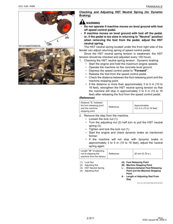
- Transaxle Checking and Adjustment
- Transaxle Separation and Removal
- Transaxle Disassembly
- PTO Clutch Disassembly
- Hydrostatic Transmission Inspection and Servicing
- Transaxle Case Inspection and Servicing
- Brake Case Component Servicing
- Mechanical PTO Clutch Servicing
- Hydraulic PTO Clutch Servicing
-
05. Front Axle — Inspection and Servicing
- Front Axle Troubleshooting
- Front Axle Servicing Specifications
- Front Axle Tightening Torques
- Front Axle Checking and Adjustment
- Front Axle Assembly Separation
- Front Axle Disassembly and Assembly
- Front Axle Component Inspection and Servicing
-
06. Power Steering System
- Power Steering Hydraulic Circuit — Mechanical PTO Configuration
- Power Steering Hydraulic Circuit — Hydraulic PTO Configuration
- Steering Controller Construction
- Power Steering Cylinder
- Steering System Troubleshooting
- Steering Servicing Specifications
- Steering Tightening Torques
- Power Steering Relief Valve Inspection
- Power Steering Cylinder Disassembly
- Steering Controller Disassembly
- Steering Component Inspection and Servicing
-
07. Hydraulic System and Grass-Collector Controls
- Hydraulic Circuit — Mechanical PTO, LD Configuration
- Hydraulic Circuit — Mechanical PTO, HD Configuration
- Hydraulic Circuit — Hydraulic PTO, LD Configuration
- Hydraulic Circuit — Hydraulic PTO, HD Configuration
- Hydraulic Pump Construction
- Hydraulic Relief Valve
- Flow Priority Valve
- Main Hydraulic Control Valve
- Hydraulic Lift Cylinder System
- Mower Lift Cylinder
- Grass-Collector Dump Cylinder — LD
- Grass-Collector Dump Cylinder — HD
- Grass-Collector Lift Cylinder — HD
- Hydraulic System Troubleshooting
- Hydraulic Servicing Specifications
- Hydraulic Tightening Torques
- Hydraulic System Checking and Adjustment
- Hydraulic Component Removal
- Hydraulic Component Disassembly
- Hydraulic Pump Inspection and Servicing
- Hydraulic Lift Cylinder Servicing
-
08. Electrical System and Diagnostics
- Electrical Wiring Diagram — G23
- Electrical Wiring Diagram — G26
- Engine Starting System
- Starting System Electrical Circuit
- Engine Starting Safety Switches
- Battery Charging System
- Charging System Electrical Circuit
- IC Voltage Regulator — Three-Pin Connector Type
- Lighting System Electrical Circuit
- Electrical Gauge Circuit
- Hour Meter and Tachometer
- Fuel Level Gauge
- Coolant Temperature Gauge
- Grass-Collector Buzzer System
- Grass-Collector Duct Switch
- Electrical System Troubleshooting
- Electrical Servicing Specifications
- Electrical Tightening Torques
- Battery Inspection and Testing
- Main Switch Checking and Adjustment
- Starter Motor Testing
- Glow Plug Checking
- Starting Safety Switch Inspection
- Operator Presence Control (OPC) Switch Testing
- Grass-Collector Duct Switch Inspection
- Grass-Collector Buzzer Testing
- Electric Fuel Pump Inspection
- Engine Stop Solenoid Testing
- Timer Relay Inspection
- Charging System Testing
- Alternator Inspection
- Combination Switch Testing
- Electrical Gauge Inspection
- Starter Motor Disassembly and Assembly
- Alternator Disassembly and Assembly
- Starter Motor Component Servicing
- Alternator Component Servicing
-
09. Mower — Mechanism and Servicing
- Rotary Mower Power Transmission
- Mower Gear Case Power Train
- Mower Lifting Mechanism
- Rotary Mower Troubleshooting
- Mower Servicing Specifications
- Mower Tightening Torques
- Mower Checking and Adjustment
- Mower Component Disassembly and Assembly
- Mower Component Inspection and Servicing
-
10. Grass Collector — Inspection and Servicing
- Grass-Collector Troubleshooting
- Grass-Collector Servicing Specifications
- Grass-Collector Tightening Torques
- Grass-Collector Inspection and Checking
- Grass-Collector Disassembly — LD Configuration
- Grass-Collector Disassembly — HD Configuration
Mechanical and Hydraulic PTO Clutches with LD/HD Grass-Collector Servicing
The workshop documentation distinguishes mechanical and hydraulic PTO clutch arrangements, including separate engagement mechanisms and servicing procedures. These differences extend to the hydraulic and steering circuit references associated with each configuration. When investigating cutting-drive engagement problems, identify the installed PTO clutch arrangement and consult the corresponding transaxle servicing information before performing adjustments or disassembly.
The grass-collector equipment is also divided into low-dump (LD) and high-dump (HD) configurations. Both arrangements have documented dumping cylinders, while the HD hydraulic references additionally identify a grass-collector lift cylinder. Separate collector disassembly procedures are provided, and the electrical system includes a collector duct switch and warning buzzer. When diagnosing lifting, dumping or collection-related faults, use the applicable hydraulic circuit together with the collector and electrical servicing sections rather than assuming that all collector configurations share identical components or operating requirements.

























Reviews
There are no reviews yet.