Overview
The Kubota KX080-4 Excavator Workshop Service Manual provides technical reference material for maintenance, component disassembly and assembly, testing and fault diagnosis. It covers machine identification, safety information, tightening torques and maintenance intervals, alongside service procedures for the front equipment, swivel frame, crawler tracks and undercarriage. Its separate Engine chapter contains specifications, dimensions, performance curves and fan-drive information.
The hydraulic chapters distinguish standard and angle-blade circuit arrangements and document the pump, load-sensing controls, valves, swivel and travel motors, hose routing, pressure and flow testing, and troubleshooting. Electrical coverage includes meter-panel and dealer diagnostic modes, engine-system error references, auto-idling, CAN communication and AUX system faults. Cabin chapters address air conditioning, refrigerant service, wipers and glass, followed by an electrical circuit diagram and connector chart.
Table of Contents
Kubota KX080-4 Manual
- 01. Information
- Safety First and Work-Safety Precautions
- Safety Label Locations and Label Maintenance
- Main Specifications and Dimensions
- 02. General
- Excavator Identification
- Engine Identification: Model, Serial Number, E4B Engine and Cylinder Number
- Muffler Assembly Identification: Part Number and Serial Number
- General Service Precautions
- Electrical Wiring, Fuses and Connector Handling
- Precautions for High-Pressure Washing
- General Nut and Bolt Tightening Torques
- Hydraulic Hose Fitting, O-Ring Adaptor and Hose Clamp Torques
- Oil and Water Capacities
- Maintenance Intervals
- 03. Machine Body
- Front Equipment: Boom Assembly and Disassembly
- Bucket, Front Pin, Front Bushing, Arm and Blade Dimensions
- Swivel Frame: Weight Assembly and Disassembly
- Cabin Removal and Mounting
- Fuel Tank and Hydraulic Oil Tank Removal and Installation
- DPF Muffler and Engine Removal and Installation
- Travel Lever, Blade Lever and Limit Switch Assembly
- Track Frame: Swivel Bearing Assembly and Disassembly
- Rubber and Iron Track Assembly and Disassembly
- Steel Track Removal and Installation Tools
- Front Idler, Grease Cylinder and Tensioner Servicing
- Track Roller and Carrier Roller Assembly and Disassembly
- Rubber and Steel Track, Idler Sprocket and Roller Dimensions
- Measuring Swivel Gear Backlash and Swivel Bearing Play
- Swivel Gear Backlash Performance
- 04. Engine
- Engine Specifications
- Engine Dimensions
- Engine Performance Curves
- Fan Drive
- 05. Hydraulic System
- Mechanism: Standard-Specification Hydraulic Circuit Diagram
- Mechanism: Angle-Blade-Specification Hydraulic Circuit Diagram
- Hydraulic Device Layout
- Pump Specifications and P3 Pump Horsepower Control Curves
- Pump Operating Principles and Horsepower Control
- Pump Load-Sensing Flow Control, Gain Control and Standby Flow
- Control Valve Specifications and Unload Valve Operation
- Control Valve Mono-Block Section and Load-Sensing Operation
- Arm Regeneration and Swing Section Operation
- Travel and Blade Open-Center Control
- Control Valve Anti-Drift Function and Signal Circuit
- P3 Bypass During Simultaneous Boom Raise and Swivel Operation
- Swivel Motor Specifications and Operating Principles
- Travel Motor Specifications and Operating Principles
- Hydraulic Cylinder Specifications and Operating Principles
- Control, Travel, Swing and Blade Pilot Valve Mechanisms
- Shockless Valves: Specifications, Function and Structure
- Unload, AUX, Angle and EP-Mode Solenoid Valves
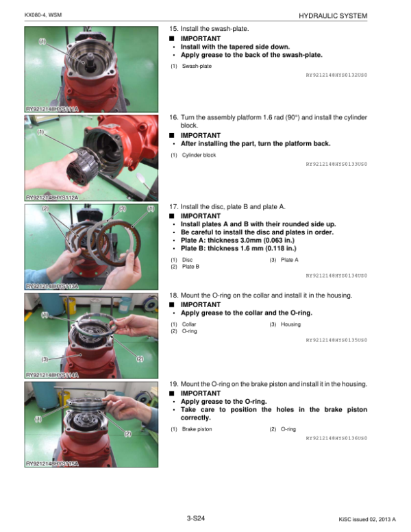
- Pump Disassembly and Assembly
- Control Valve Removal, Disassembly and Assembly
- Swivel Motor Removal, Disassembly, Assembly and Special Tools
- Swivel Joint Removal, Disassembly and Assembly
- Travel Motor Removal, Disassembly, Assembly and Special Tools
- Hydraulic Cylinder Tightening Torque
- Control, Travel, Swing and Blade Pilot Valve Disassembly and Assembly
- Pilot Valve Special Tools
- Shockless Valves and Swivel Shuttle Valve Servicing
- Unload, AUX Proportional, Angle and EP-Mode Solenoid Valve Servicing
- High-Pressure Hose Routing: Delivery, PLS, Front and Boom Circuits
- High-Pressure Hose Routing: Undercarriage and Angle Blade
- Low-Pressure Suction and Drain Hose Routing
- Pilot Hose Routing and Valve Port Connections
- Piston Pump Air Bleeding and Hydraulic Pressure Release
- Manual Boom Lowering Procedure
- Main Pump Flow and AUX Proportional/Discharge Flow Measurements
- Main, Pilot, EP Solenoid, Overload and Swivel Relief Pressure Tests
- Load-Sensing Differential Pressure Spring Adjustment
- Swivel Motor Drain Volume, Block Performance and Speed Tests
- Travel Motor Drain Volume, Block Performance, Speed and Drift Tests
- Hydraulic Cylinder Operating Time, Drift and Swing Deviation Measurements
- Hydraulic Performance Standards: Pump and AUX Flow Rates
- Hydraulic Performance Standards: Relief Pressure, Swivel, Travel and Cylinder Speed
- Troubleshooting All Actuators and Front Systems
- Troubleshooting Travel, Swivel and Multiple Operations
- 06. Electrical System
- Electrical Device Layout, Wiring Routes and Connector Precautions
- Meter Panel Names, Functions and User Settings
- Meter Panel Log Records, Periodic Checks, Clock and AUX Flow Settings
- Service Dealer Settings: Crane Mode and Japan-Specification Arm Control Mode
- Service/Dealer Mode Diagnosis and Settings
- Settings After Meter, Main ECU or Battery Replacement
- Meter Panel Warning Messages and Error History
- PM Clog-Level Information and Engine-System Error Numbers
- Power and Ground, Starting and Stopping Device Inspections
- Relay Layout and Start-Up Equipment Troubleshooting
- Electrical Fault-Diagnosis Procedures and Circuit Tester Checks
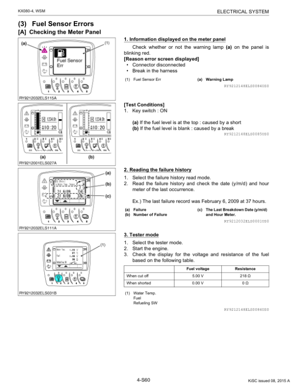
- Meter Panel Troubleshooting: Engine Oil Pressure, Charging and Fuel Sensor
- Lever Lock, Two-Speed Travel and Angle-System Diagnostics
- Auto-Idling System Diagnosis and AI Switch/Pressure Switch Testing
- Anti-Theft System Error Diagnosis
- Power-Supply Diagnosis: Overvoltage and 5 V Short Circuit
- CAN Communication Error Diagnosis
- AUX1/AUX2 (Thumb) System Error Diagnosis
- ECO/EP Mode System Error Diagnosis
- 07. Cabin
- Air-Conditioning System Structure and Operation
- Compressor, Air-Conditioner Unit, Condenser and Receiver
- Pressure Switch, Air-Conditioning Electrical Circuits and Relays
- Blower Switch and Wiper System
- Cabin Troubleshooting and Service Specifications
- Cabin Tightening Torques
- Refrigerant-System Repair Precautions and Service Tools
- Refrigerant-System Inspection Using a Manifold Gauge
- Refrigerant Recovery, Evacuation and Charging
- Compressor, Relays, Blower Motor, Resistor and Switch Checks
- Temperature-Control Servo Motor and Pressure Switch Checks
- Air-Conditioning Unit and Compressor Assembly/Disassembly
- Air-Conditioning and Heater Hose Routing
- Condenser and Electric Fan Removal and Installation
- Window Washer: Switch, Wiper Motor and Washer Motor
- Glass Removal and Installation, Including Right-Side Window
- Front Window Closing-Lock and Opening-Lock Adjustments
- 08. Electrical Circuit Diagram
- 09. Connector Chart
Hydraulic Circuit Variants and Diagnostic References
The hydraulic section includes separate circuit diagrams for standard and angle-blade specifications, as well as angle-blade hose-routing and solenoid-valve references. Select the diagrams and related service information that correspond to the machine’s fitted equipment. For electrical fault tracing, the meter-panel message and error-history tables are located in the Electrical System chapter, with a separate circuit diagram and connector chart at the end of the manual.




























Reviews
There are no reviews yet.