Overview
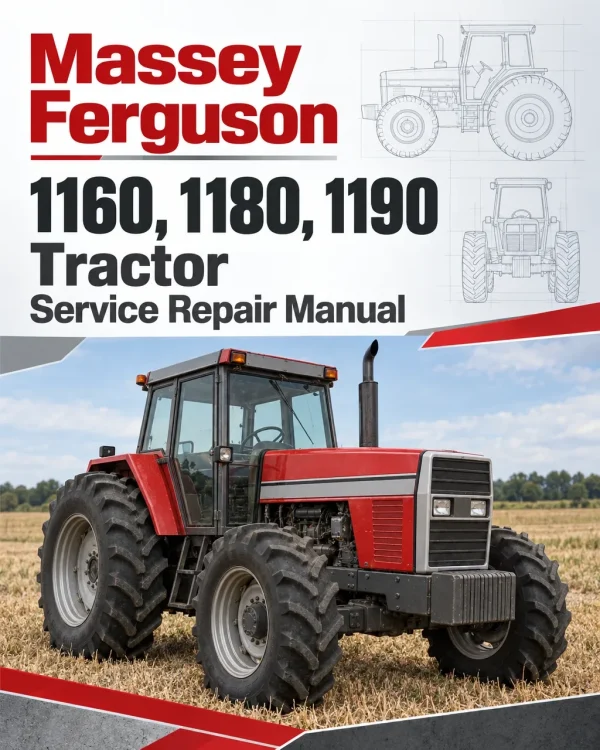
The Massey Ferguson 1160, 1180 and 1190 Tractor Workshop Service Repair Manual provides detailed technical information for servicing, maintaining, troubleshooting and repairing these Massey Ferguson agricultural tractors. The documentation covers tractor specifications, sheet metal and three-point hitch components, major assembly separation, diesel engine servicing, fuel and cooling systems, clutch assemblies, transmission components, front and rear axles, braking systems, power steering, hydraulics and electrical equipment.
Workshop coverage includes tractor splitting procedures, fuel injection pump timing and servicing, clutch inspection and adjustment, Power Shuttle transmission controls, PTO hydraulic operation, four-wheel-drive components, differential lock servicing, hydraulic lift adjustments, steering gear repairs and electrical system maintenance. Additional technical references include fuel filter replacement, hydraulic pump overhaul, brake adjustments, pressure control valves, engine removal, component disassembly and reassembly, and troubleshooting information.
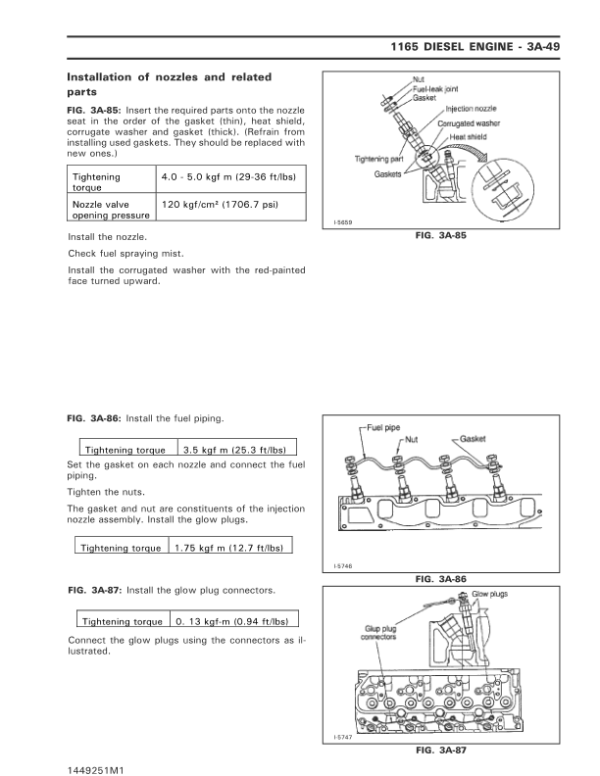
Important Information: The source publication also contains dedicated Massey Ferguson 1165 engine and power steering sections. Fuel system procedures distinguish between MF 1160/1180 and MF 1190 configurations. Verify the tractor model, transmission and installed equipment before following a service procedure.
Table of Contents
Massey Ferguson 1160, 1180, 1190 Tractor Service Manual
- 01. Introduction
- 01A. Sheet Metal and Three-Point Hitch
- 01B. Major Components
- General Precautions for Separation and Reinstallation
- Precautions for Installing Standardized Parts
- Roller and Ball Bearings
- Oil Seals and O-Rings
- Snap Rings and Spring Pins
- Cotter Pins, Bolts and Nuts
- Adhesives and Component Sealants
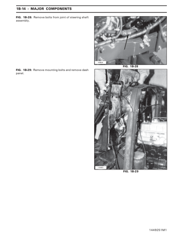
- Separation of Major Components
- Front Wheel Drive Shaft (4WD)
- Front Axle and Front Axle Bracket – Removal and Installation
- Front Axle with Front and Rear Brackets
- Splitting the Tractor Between the Engine and Front Transmission
- Engine Separation from Chassis
- Splitting the Front Transmission and Spacer Transmission
- Splitting the Spacer Transmission and Differential
- Rear Axle Housing at Differential – Removal and Installation
- Hydraulic Cylinder Cover – Removal and Installation
- 02A. Engine
- 02B. Fuel System – MF 1160, 1180 and 1190
- Fuel System – MF 1160 and MF 1180
- Fuel Injection Pump Data and Specifications
- Fuel System – MF 1190
- Zexel Diesel Kiki NP-VE4 Injection Pump – MF 1190
- Fuel Injection Nozzles
- Injector Lines – Removal and Installation
- Primary Fuel Filter – MF 1160 and MF 1180
- Secondary Fuel Filter – MF 1160 and MF 1180
- Fuel System Air Bleeding – MF 1160 and MF 1180
- Primary Fuel Filter – MF 1190
- Sediment Fuel Filter and Water Draining – MF 1190
- Fuel Filter Cartridge – MF 1190
- Fuel System Bleeding – MF 1190
- Injection Pump Removal and Installation – MF 1160 and MF 1180
- Injection Pump Installation – MF 1160 and MF 1180
- Spill Timing the Injection Pump – MF 1160 and MF 1180
- Fuel Cut-Off Solenoid Adjustment
- Fuel Injection Pump – MF 1190
- Injector Nozzle Removal and Installation
- Injection Nozzle Testing
- Injection Nozzle Pressure Adjustment
- Nozzle Disassembly and Reassembly
- Injection Nozzle Needle Inspection
- Nozzle Lapping Procedure
- Main Fuel Tank – Removal and Installation
- Lower Fuel Tank – Removal and Installation
- 02C. Cooling System and Air Cleaner
- 03A. Iseki Diesel Engine – MF 1165 Only
- 04A. Clutch
- General Description
- Clutch Specifications
- Main Clutch – Removal and Installation
- Main Clutch Overhaul
- Main Clutch Inspection
- Pressure Plate Inspection
- Pressure Spring Adjustment
- Pressure Spring Inspection
- Clutch Reassembly
- Clutch Release Bearing – Removal and Installation
- Release Bearing Inspection and Reassembly
- Clutch Cross Shaft and Related Parts
- Clutch Cross Shaft Disassembly and Inspection
- Clutch Pedal Free-Play Adjustment
- Clutch Rod Linkage – Removal and Installation
- Clutch Troubleshooting
- 05A. Transmission
- 05B. Power Shuttle
- Power Shuttle Specifications
- Engine and Transmission Specifications
- Power Take-Off Specifications
- Hydraulic and Electrical Specifications
- Fluid Capacities
- Wheel Tread Width Settings
- Maximum Axle Loading
- General Dimensions
- Power Shuttle Lever
- Power Shuttle Lever Operation
- Power Shuttle Operating Precautions
- Power Shuttle Lever and Switch Installation
- Power Shuttle Linear Shifting Switches
- Power Shuttle Switch Adjustment
- Hydraulic Fluid Flow
- Main Hydraulic Circuit
- Auxiliary Hydraulic Circuit
- Hydraulic System Piping
- Pipe Joint Tightening Torques
- Reducing Valve and Piping Locations
- Reducing Valve Operation
- PTO Solenoid Operation
- Timer Unit Control
- PTO Timer Relay Location
- Reverse Valve Operation
- 05B2. Power Shuttle – Additional Service Section
- 06A. Front Axle
- 07A. Rear Axle and Brakes
- General Description
- Rear Axle and Brake Specifications
- Final Drive Gear – Removal and Installation
- Axle, Axle Seal and Bearings
- Brake Disc – Removal and Installation
- Brake Overhaul
- Rear Axle Housing Removal
- Brake Friction Plate Inspection
- Brake Actuator Inspection
- Brake Separator Plate Inspection
- Brake Reassembly
- Differential Lock Clutch
- Differential Lock Clutch – Removal and Installation
- Rear Axle Housing Replacement
- Brake Boot – Removal and Installation
- Brake Adjustment
- Brake Rod – Removal and Installation
- Brake Pedal – Removal and Installation
- Parking Brake – Removal and Installation
- Rear Axle and Brake Troubleshooting
- 08A. Power Assist Steering
- General Description
- Power Assist Steering Specifications
- Steering Gear Pump
- Power Assist Steering Unit
- Power Assist Steering Reservoir
- Steering System Operation
- Neutral Position
- Steering Right
- Steering Left
- Steering Without Hydraulic Assistance
- Power Steering Unit – Removal and Installation
- Power Steering Unit Overhaul
- Power Steering Unit Disassembly
- Worm Shaft
- Ball-Nut Inspection and Service Standards
- Sector Shaft
- Steering Gear Case
- Steering Unit Reassembly
- Steering System Air Bleeding
- Relief Valve Pressure Adjustment
- Power Steering Gear Pump – Removal and Installation
- Gear Pump Overhaul and Disassembly
- Gear Pump Inspection and Repair
- Pump Gears and Bushings
- O-Rings and Oil Seals
- Pump Cover Bolt Tightening Sequence and Torque
- Inspection After Gear Pump Reassembly
- Steering Wheel – Removal and Installation
- Steering Drive Shaft – Removal and Installation
- Steering Reservoir – Removal and Installation
- Power Steering Troubleshooting
- 08B. Power Steering System – MF 1165 Only
- Power Steering System Construction
- Steering Components
- Integral Orbitrol Steering Unit
- Steering Unit Disassembly
- Disassembly of Rotor Side
- Disassembly of Control Side
- Steering Component Inspection
- Steering Unit Reassembly
- Reassembly of Control Side
- Reassembly of Gerotor Side
- Power Steering Troubleshooting
- 09A. Hydraulic System
- General Description
- Hydraulic System Specifications
- Hydraulic Pump for Three-Point Hitch
- Transmission and Hydraulic Oil Replacement
- Transmission Cartridge Filter Replacement
- Hydraulic Suction Filter – Removal and Installation
- Hydraulic Pump – Removal and Installation
- Hydraulic Pump Overhaul and Disassembly
- Hydraulic Pump Inspection and Repair
- Pump Gears, O-Rings and Oil Seals
- Hydraulic Pump Reassembly
- Inspection After Hydraulic Pump Reassembly
- Hydraulic Linkage System
- Hydraulic Linkage Overhaul and Reassembly
- Draft Spring or Housing – Removal and Installation
- Lift Shaft and Crank – Removal and Installation
- Hydraulic Cylinder and Piston
- Hydraulic Linkage System Adjustment
- Position Control Adjustment
- Draft Control Adjustment
- Draft and Position Control Operation
- Main Hydraulic Control Valve
- Main Spool
- Unloading Valve and Compensator
- Holding Check Valve
- Pilot Spool
- Control Valve Neutral Position
- Control Valve Lifting Position
- Control Valve Lowering Position
- Lifting-to-Neutral Operation
- Control Valve – Removal and Installation
- Control Valve Overhaul
- Control Valve Disassembly and Reassembly
- Lift Assist Cylinder – MF 1180 and MF 1190
- PTO Control Valve
- PTO Solenoid and Changeover Valve
- PTO Pressure-Reducing Valve
- PTO Control Valve Operation
- PTO Valve Flow Divider – Removal and Overhaul
- Pressure Control Valve
- PTO Pressure Control Valve – Removal and Installation
- PTO Pressure Control Valve Overhaul
- Main Relief Valve – Removal and Overhaul
- Main Relief Valve Pressure Check
- Cylinder Protection Relief Valve
- Flow Control Valve – Slow Return Check Valve
- Slow Lowering Check Valve
- Hydraulic Cylinder Cover Replacement
- Piston Lift Rod – Removal and Installation
- Remote Hydraulic Control – Optional
- Remote Hydraulic Control Valve
- Single-Acting and Double-Acting Oil Flow
- Remote Hydraulic Control Ports
- Remote Control Valve – Removal and Overhaul
- Hydraulic System Troubleshooting
- 10A. Electrical System
- 10A2. Electrical System – Additional Section
- 10B. Starter
- 10C. Alternator
PowerShuttle, Hydraulic Lift and Rear Axle Service
The Massey Ferguson 1160, 1180 and 1190 workshop documentation includes technical procedures for fuel injection pump servicing, clutch repairs, Power Shuttle controls, rear axle brake maintenance, power assist steering and hydraulic lift systems. Model-specific fuel system references, transmission service information, hydraulic valve procedures and component troubleshooting help technicians identify the appropriate maintenance and repair instructions.























Reviews
There are no reviews yet.