Overview
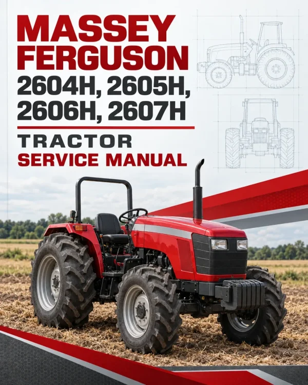
The Massey Ferguson 2604H, 2605H, 2606H and 2607H Tractor Workshop Service Manual provides technical information for maintaining, troubleshooting and repairing these agricultural tractors. It includes specifications, component identification, inspection procedures, adjustments and detailed workshop servicing instructions.
Coverage includes the SJV326 engine, two-wheel-drive and G4 four-wheel-drive front axles, dual and split-torque clutches, 8×2 and 8×8 transmissions, rear axle and braking assemblies, steering, hydraulics and electrical equipment. Separate chapters address live and independent power take-off systems, the starter motor and alternator.
Safety: The manual includes workshop safety information and a dedicated safety section within the four-wheel-drive front axle material. Review the applicable instructions before tractor separation, component removal or repair work.
Table of Contents
Massey Ferguson 2604H, 2605H, 2606H, 2607H Manual
-
1. Introduction and Safety
- Introduction
- Safety in Workshop
-
2. Miscellaneous Data
- Bolt Torque Specifications (Inch)
- Bolt Torque Specifications (Metric)
- Conversion Tables
-
3. Tractor Identification and Specifications
- Tractor Identification
- Specifications
-
4. Splitting the Tractor
- Specifications
- Splitting the Tractor Between the Front Axle and Engine
- Splitting the Tractor Between the Engine and Transmission
- Splitting the Tractor Between the Transmission and Rear Transmission
-
5. Sheet Metal
- General Description and Specification
- Bonnet
- Air Cleaner
- Dry-Type Air Cleaner Overhauling
- Head Lamp Mounting Bracket
- Front Grill
- Hinge Mounting Bracket
- Lip Seal
- Gas Strut
- Radiator Seal
- Lock Plate
- Battery Tray
- Instrument Panel Cover
- Binnacle Assembly
- Fender and ROPS
- Footstep
- Fuel Tank
- Seat Adjustment
- 6. Engine SJV326
-
7A. Front Axle – 2WD
- Specifications
- Front Wheel Toe-In – Hydrostatic Steering
- Front Hub Adjustment
- Front Hub Overhaul
- Spindle Shaft
- Spindle Housing
- Axle Beam Assembly
- Front Engine Support
- Front Axle Support Bush
-
7B. Front Axle – 4WD (G4)
- Safety Instruction
- General Information
- General Specification
- Axle Groups Description
- Technical Features
- Removal and Refitment – 4WD Assembly
- Removal and Refitment – Planetary Carrier
- Removal and Refitment – Wheel Hub Ring Gear
- Removal and Refitment – Wheel End Assembly
- Removal and Refitment – Swivel Housing
- Removal and Refitment – Differential Assembly
- Removal and Refitment – Settings
- Troubleshooting
- Special Tools
-
8A. Dual Clutch
- Specification
- General Description
- Clutch Pedal Free Play
- PTO Clutch
- Dual Clutch Assembly
- Clutch Release Bearing
- Clutch Release Mechanism
- Flywheel Pilot Bearing
- Fault Finding Chart
-
8B. Split Torque Clutch
- Specification
- General Description
- Split Torque Clutch Assembly
- Split Torque Clutch Overhauling
- Flywheel Pilot Bearing
-
9A. 8×2 Transmission
- Specification
- General Description – Side Shift
- Main Lever Assembly – Side Shift
- Planetary Lever Assembly – Side Shift
- Selector Rails and Forks – Side Shift
- Epicyclic Unit – Side Shift
- Clutch Release Mechanism
- Main Drive Housing and PTO Pinion Shaft
- PTO Drive Shaft Bearing Housing
- Main Shaft, Countershaft and Gears
-
9B. 8×8 Transmission
- Specification
- General Description
- Main Lever Assembly – Side Shift
- Planetary Lever Assembly – Side Shift
- Shuttle Control Lever
- Selector Rails and Forks – Side Shift
- Epicyclic Unit – Side Shift
- Clutch Release Mechanism
- Main Drive Housing and PTO Pinion Shaft
- PTO Drive Shaft Bearing Housing
-
9C. Transfer Gearbox and Drive Shaft
- Specification
- General Description – Transfer Gearbox
- Drive Shaft – Removal
- Drive Shaft – Overhaul
- Transfer Gears – Overhaul
- Transfer Gearbox – Removal
- Transfer Gearbox – Overhaul
- Drive Shaft Seal Replacement – All Models
-
10A. Rear Axle and Oil-Immersed Brakes
- General Description
- Rear Wheel Stud
- Epicyclic Unit Outer Housing and Ring Gear
- Epicyclic Planet and Sun Gear
- Epicyclic Unit
- Epicyclic Preload
- Axle Housing Left-Hand Side
- Axle Housing Right-Hand Side
- Axle Shaft – Direct Drive
- Axle Shaft – Planetary Drive
- Left-Hand Carrier Plate
- Right-Hand Carrier Plate
- Left-Hand Brake Actuator Housing
- Right-Hand Brake Actuator Housing
- Brake Adjusting and Balancing
- Left-Hand Brakes Servicing
- Right-Hand Brake Servicing
- Differential Lock Actuator Mechanism
- Differential Lock Coupler Cap
- Differential Lock Preload Checking and Adjustment
- Right-Hand Differential Bearing
- Differential Unit
- Differential Bearing Left-Hand
- Differential Unit Removal
- Crown Wheel
- Pinion Assembly
- Rear Drive Shaft
- Parking Brake Servicing
-
10B. Rear Axle and Drum Brakes
- Specification
- General Description
- Axle Shaft – Drum Brake
- Axle Shaft Direct Drive Drum Brake
- Axle Housing Assembly
- Lower Link Pin – Drum Brake
- Crown Wheel Pinion Specification
- General Description
- Differential Unit
- Crown Wheel and Pinion Removal
- Differential Preload Check
- Drum Brake Specification
- General Description
- Drum Brake Adjustment
- Drum Brake Removal
- Drum Brake Assembly – Removal
- Rear Drive Shaft
-
11A. Hydraulics
- Specification
- General Description
- Control Spring Assembly – Removal
- Control Spring Assembly – Overhaul
- Hydraulic Lift Cover – Removal
- Hydraulic Lift Cover – Overhaul
- Hydraulic Lift Cylinder – Overhaul
- Quadrant and Support Assembly – Overhaul
- Hydraulic Static Adjustments
- Hydraulic Pressure Test
- Hydraulic Pump Assembly – Removal
- Hydraulic Pump Assembly – Overhaul
- Hydraulic Relief Valve – Removal
- Right-Hand Side Cover – Removal
- Right-Hand Side Cover – Overhaul
- Specifications – Suction Strainer Assembly
- Suction Strainer – Overhaul
-
11B. Auxiliary Hydraulics
- Spool Valve
- Spool Valve – Specification
- Spool Valve – General Description
- Spool Valve Assembly – Removal
- Spool Valve Section – Removal
- Double Spool Valve Assembly – Removal
- Double Spool Valve Section – Removal
- Auxiliary Pump Flow and Pressure Test
- Drawbar and Linkage
- Drawbar and Linkage – Specification
- Drawbar and Linkage – General Description
- Rod Lift
- Turn Buckle
- Swinging Drawbar
- Swinging Drawbar Adjustment
-
11C. Steering System
- Specification
- General Description
- Procedure for Oil Filling and Air Bleeding in Hydrostatic Steering
- Steering Pump Assembly – Removal
- Steering Pump – Overhaul
- Hydraulic Gear Pumps – Causes of Failure
- Procedure for Dismantling Hydraulic Steering Unit from Tractor
- Steering Unit – Overhaul
- Drag Links and Tie Rods – Overhaul
- Steering Rams
- Steering Cylinder – Overhaul
- 12A. Live Power Take-Off
- 12B. Independent Power Take-Off
-
13A. General Electrical
- Specification
- General Description
- Servicing the Electrical System
- Preliminary Checks
- Routine Maintenance
- Maintenance-Free Battery
- Preparation of Dry-Charge Batteries
- Recharging in Servicing
- Boost Charging
- Battery Removal and Refitment
- Headlight Beam Adjustment
- Removal and Refitment of Headlight Bulb
- Removal and Refitment of Flashing Indicator Bulb
- Removal and Refitment of Turn Indicator Bulb
- Removal and Refitment of Work Lamp Bulb
- Check – Fuel Tank Sender Unit
- Removal and Refitment of Starter Switch
- Removal and Refitment of Light Switch
- Removal and Refitment of Turn Indicator Switch
- Check Air Cleaner Restriction Sensor
- Removal and Refitment of Trailer Socket
- Fuses and Relays
- Arrangement of Fuses
- Check Relays
- Instrument Cluster
- Removal and Refitment of Instrument Cluster
- Instrument Cluster – Overhauling
- Wiring Diagram (2WD / 4WD)
- Fault Diagnosis
- 13B. Starter Motor
- 13C. Alternator
Selecting the Correct Axle and Drivetrain Procedures
The documentation distinguishes two-wheel-drive front axle servicing from G4 four-wheel-drive axle procedures, including component removal, refitting and differential servicing. Separate chapters cover dual and split-torque clutches, 8×2 and 8×8 transmissions, and the transfer gearbox. Confirm the tractor’s installed configuration before selecting the corresponding adjustment or overhaul instructions.
Rear axle servicing is divided between oil-immersed and drum-brake assemblies, while the hydraulic chapters address lift hydraulics, auxiliary spool valves and hydrostatic steering. Refer to the tractor identification and specification sections when checking the applicable components and service requirements.


















Reviews
There are no reviews yet.