Overview
The Massey Ferguson MF 9306 and MF 9407 (T)(H) Telescopic Handler Workshop Service Manual provides system-specific guidance for inspection, servicing, troubleshooting and repair of the listed Massey Ferguson telescopic handlers. The documentation covers routine maintenance, hydraulics, hydrostatic transmission components, axles and drive systems, boom and chassis assemblies, electrical controls, engine repairs, heating and air conditioning, and machine specifications.
Workshop subjects include hydraulic lift, tilt, extension and self-leveling cylinder overhaul; hydrostatic pump and motor repair; planetary drives, differentials, brakes and gearbox servicing; boom wear pad and attachment carrier replacement; engine timing, fuel injection and cylinder-head work; and electrical sensor calibration. The manual also lists LLMI/LLMC diagnostic procedures, refrigerant system service, torque charts, fluid requirements and designated service-tool connections.
Notice: The hydraulic section distinguishes a standard single-speed fan motor from an optional variable-speed version, and labels the hydraulic accumulator as “if equipped.” Select procedures to match the machine’s installed components and identification details.
Safety: The source includes safe operation, machine lifting and blocking, fire prevention, welding, hydraulic and fuel-system precautions, and approved boom-stop procedures. Review the relevant safety instructions before performing service work.
Table of Contents
Massey Ferguson MF 9306, 9407 (T)(H) Manual
-
01. Safety and Maintenance
- Foreword, safe operation and qualified operator requirements
- Avoiding silica dust
- Fire prevention during maintenance and operation
- Fire prevention — electrical, hydraulic and fueling precautions
- Fire prevention — starting, spark arresters, welding and grinding
- Fire extinguishers
- Telescopic handler identification and serial number locations
- Engine and other serial numbers
- Delivery report and machine identification
- Lifting and blocking the telescopic handler
- Operator cab, door, windows and cab light
- Trailer loading, unloading and securement
- Towing procedures
- Service schedule
- Air cleaner filter element replacement
- Engine cooling system cleaning, coolant replacement and level checks
- Fuel specifications and biodiesel blend information
- Fuel tank filling and primary/secondary fuel filters
- Bleeding air from the fuel system
- Engine oil checking, lubricant chart, oil and filter replacement
- Hydraulic/hydrostatic oil level, fluid chart and fluid replacement
- Hydraulic/hydrostatic filter and charge filter replacement
- Hydraulic reservoir fill and breather cap
- Front and rear planetary carrier oil maintenance
- Front and rear differential oil maintenance
- Gearbox oil checks and replacement
- Telescopic handler lubrication points
- Attachment carrier inspection and maintenance
- Tyre pressure, mounting, rotation and wheel nut maintenance
- Approved boom stop installation and removal (if equipped)
- Engine cover opening and closing
- Engine stopping and operator exit procedure
- Emergency exit using the rear cab window
- Tractor-homologated emergency exit using the right rear window
- Machine storage and return to service
- Remote start tool kit MEL1563 and service harnesses MEL1565/MEL1566
- Remote start tool kit 7003031, tool 7003030 and service harnesses 6689747/6689746
- Remote start service procedure
-
02. Hydraulic System
- Hydraulic system information, troubleshooting and tightening procedures
- Lift cylinder removal, installation, parts identification, disassembly and assembly
- Self-leveling cylinder removal, installation, parts identification and overhaul
- Self-leveling cylinder lock valve — removal and installation
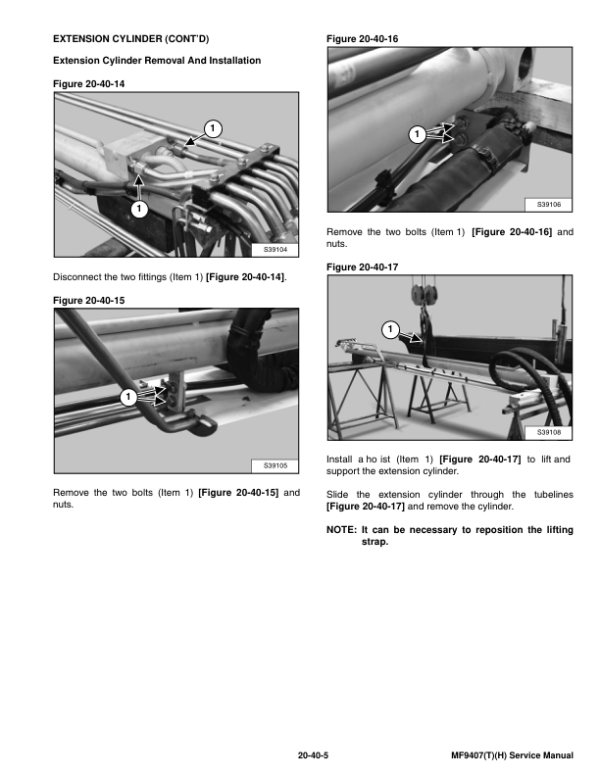
- Extension cylinder group removal and installation
- Extension cylinder upper tubelines and tubeline tray
- Extension cylinder parts identification, disassembly and assembly
- Tilt cylinder removal, installation, parts identification and overhaul
- Front and rear steering cylinder removal, disassembly, assembly and installation
- Gear control cylinder removal, parts identification, disassembly and installation
- Main relief valve testing and adjustment
- Main relief valve removal and installation
- Hydraulic manifold removal, parts identification and disassembly/reassembly
- Brake valve removal and installation
- Hydraulic gear pump removal, parts identification and overhaul
- Hydraulic fan motor — standard single-speed version
- Hydraulic fan motor — optional variable-speed version
- Hydraulic reservoir removal and installation
- Steering valve removal and installation
- Hydraulic control valve controller and valve-section troubleshooting
- Hydraulic control valve removal, parts identification and overhaul
- Control valve inlet/outlet section disassembly and assembly
- Control valve lifting section disassembly and assembly
- Control valve tilting section disassembly and assembly
- Control valve telescoping section disassembly and assembly
- Control valve auxiliary section disassembly and assembly
- Control valve end housing disassembly and assembly
- Port relief valve adjustment and replacement
- Parking brake valve removal and installation
- Hydraulic accumulator removal and installation (if equipped)
-
03. Hydrostatic System
- Hydrostatic system troubleshooting chart
- Replenishing valve function
- Hydrostatic oil cooler description
- Hydrostatic drive motor removal and installation
- Hydrostatic drive motor parts identification
- Hydrostatic drive motor disassembly, inspection and assembly
- Hydrostatic pump removal and installation
- Hydrostatic pump parts identification
- Hydrostatic pump shaft disassembly
- Hydrostatic pump relief valve disassembly and assembly
- Charge pump disassembly
- Piston pump disassembly
- Solenoid block disassembly
- Hydrostatic pump component inspection
- Piston pump reassembly
- Charge pump reassembly
- Solenoid block reassembly
- Hydrostatic pump shaft reassembly
-
04. Drive System, Axles and Brakes
- Drive system troubleshooting
- Front axle and differential — planetary carrier parts and disassembly
- Front axle — steering knuckle and drive axle disassembly
- Front axle — brake assembly and differential disassembly
- Front axle — bevel pinion disassembly and reassembly
- Front axle — differential, brakes, drive axle and steering knuckle assembly
- Front axle — planetary carrier reassembly and special tools
- Rear axle and differential — planetary carrier and steering knuckle components
- Rear axle — steering knuckle and differential disassembly
- Rear axle — bevel pinion disassembly and reassembly
- Rear axle — differential, steering knuckle and planetary carrier assembly
- Rear axle service tools
- Front axle removal and installation
- Front axle toe-in adjustment
- Parking brake release for towing and adjustment
- Parking brake cylinder and disc removal/installation
- Steering angle adjustment
- Front and rear driveshaft removal and installation
- Service brake description and hydraulic circuit bleeding
- Rear axle removal and installation
- Gearbox removal and installation
- Gearbox parts identification, disassembly and reassembly
-
05. Mainframe and Boom Components
- Operator cab removal and installation
- Operator seat removal and installation
- Fixed boom removal and installation
- Inner boom removal and installation
- Front boom wear pad removal and installation
- Rear boom wear pad removal and installation
- Engine cover and gas support cylinder removal/installation
- Fuel tank removal and installation
- Quick-Tach attachment carrier removal and installation
- Counterweight removal and installation
- Fender removal and installation
- Steering column cover removal and installation
- Dashboard cover removal and installation
- Joystick panel removal and installation
-
06. Electrical System and Analysis
- Electrical system information and troubleshooting chart
- Fuse and relay location and identification
- Battery removal and installation
- Using a booster battery for jump-starting
- Alternator removal and installation
- Alternator belt adjustment and replacement
- Starter motor testing, removal and installation
- Rear and front light removal and bulb replacement
- Turn signal lever removal and installation
- Instrument display removal and installation
- Left and right instrument panels removal and installation
- Boom angle sensor removal and calibration
- Front, top and rear wiper motor removal and installation
- Pedal assembly removal and installation
- Inching sensor removal and calibration
- Service PC connection using remote start tool MEL1563
- Service PC connection using remote start tool 6689778
- Fuel level sender removal and installation
- Joystick removal and installation
- LLMI / LLMC system calibration and calibration test
- LLMI / LLMC system failure reports and component identification
- LLMS removal and installation
- LLMC removal and installation
-
07. Engine Service
- Engine technical specifications and troubleshooting
- Engine speed control removal and installation
- Muffler removal and installation
- Air cleaner housing removal and installation
- Coolant expansion tank removal and installation
- Oil cooler, intercooler and radiator removal/installation
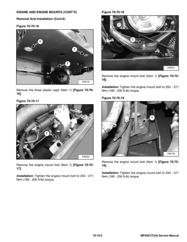
- Engine and engine mounts removal and installation
- Fuel injection pump removal and installation
- Fuel injector removal and installation
- Fuel lift pump inspection and replacement
- Engine cylinder compression testing
- Glow plug testing, removal and installation
- Engine timing procedure
- Engine/hydrostat assembly removal and installation
- Flywheel and flywheel housing removal and installation
- Flywheel inspection and ring gear replacement
- Turbocharger troubleshooting, description and replacement
- Exhaust manifold, injector cover and rocker cover removal/installation
- Cylinder head removal, inspection and installation
- Rocker shaft disassembly and reassembly
- Engine valve and valve spring inspection
- Valve depth and valve guide inspection
- Valve guide removal and installation
- Valve seat cutting and assembly
- Valve spring replacement with cylinder head installed
- Engine valve clearance adjustment
- Camshaft and timing gear servicing
- Timing cover, crankshaft pulley and front oil seal servicing
- Timing case and gear removal and installation
- Camshaft and tappets removal and installation
- Piston and connecting rod removal and disassembly
- Piston ring end gap and groove clearance inspection
- Connecting rod inspection and bushing replacement
- Piston and connecting rod assembly and installation
- Piston height inspection
- Crankshaft and main bearing removal, inspection and installation
- Rear crankshaft oil seal and seal housing servicing
- Crankshaft end play inspection
- Cooling system description and thermostat testing
- Thermostat and water pump removal and installation
- Engine lubricating oil cooler removal and installation
- Engine lubrication system description
- Oil filter adapter, oil pan, screen and pickup tube servicing
- Engine oil pump and oil pressure relief valve overhaul
- Engine block disassembly, inspection and assembly
- Piston cooling jet removal, installation and alignment
- Cylinder liner inspection, removal and installation
-
08. Heating, Ventilation and Air Conditioning (HVAC)
- Air conditioning system flow, operating principles and chart
- HVAC component identification
- Air conditioning safety equipment
- Cab filter element removal and installation
- Air conditioning drive belt adjustment and replacement
- Condenser cleaning and evaporator/heater coil maintenance
- Basic troubleshooting for poor air conditioning performance
- HVAC electrical system checks
- General air conditioning service guidelines
- Compressor oil inspection
- Component replacement and refrigerant leak information
- Air conditioning system troubleshooting chart
- Temperature/pressure reference chart
- Air conditioning service chart
- Refrigerant recovery, reclamation and system charging
- Air conditioning compressor removal and installation
- Compressor clutch disassembly and reassembly
- Condenser removal and installation
- Receiver/drier removal and installation
- Pressure switch removal and installation
- Evaporator/heater unit removal and installation
- Expansion valve removal and installation
- Thermostat description, removal and installation
-
09. Technical Specifications and Torque Data
- Telescopic handler dimensions, performance and weights
- Engine, control and drive system specifications
- Traction, steering and brake specifications
- Fluid capacities and hydraulic system specifications
- Electrical system and instrument panel specifications
- Environmental specifications
- Axle and boom tightening torques
- Drive box and drive motor tightening torques
- Engine and hydraulic pump tightening torques
- General SAE bolt tightening torque chart
- General metric bolt tightening torque chart
- O-ring face seal connection specifications
- Straight-thread O-ring fitting specifications
- Hydraulic tubing and hose specifications
- Hydraulic port seal fittings
- Hydraulic/hydrostatic fluid specifications
- Decimal and millimetre equivalents
- U.S.-to-metric conversion chart
- 10. Alphabetical Index
Service-Tool Connections and Electrical Calibration References
The electrical section identifies separate service PC connection references for remote start tools MEL1563 and 6689778. Its LLMI/LLMC coverage includes system calibration, calibration testing, failure reports, component identification, and LLMS/LLMC removal or installation. These are distinct references from routine instrument, lighting and sensor service.
Boom angle and inching sensors each have their own calibration entries. When locating a diagnostic procedure, first identify whether it concerns the LLMI/LLMC system, a specific sensor or a service-tool connection, then refer to that section of the manual.




























Reviews
There are no reviews yet.