Overview
The Kubota R420A, R520A, R420S and R520S Wheel Loader Workshop Service Manual provides technical documentation for maintenance, inspection, troubleshooting and component repair of these Kubota wheel loaders. The workshop reference covers general safety, machine specifications, articulated frame assemblies, engine servicing, hydraulic systems, braking equipment, power train components, electrical controls and backhoe equipment. The documentation also includes technical references for model changes, regional configurations and machine-specific service procedures.
The workshop chapters address front attachment installation, center-pin assemblies, LST hydraulic pump and motor operation, hydraulic pressure and flow testing, negative braking systems, limited-slip differentials, steering controls, electrical fault diagnosis and backhoe hydraulic servicing. Engine coverage includes emissions-related specifications, turbocharger information and an incorporated engine workshop section. Mechanism and Service divisions distinguish system construction and operation from troubleshooting, testing, adjustment, disassembly and reassembly, with additional technical references in the Supplement section.
Safety: Review the general safety precautions before servicing, disassembling or reassembling the machine. The documentation identifies critical safety and functional processes, including post-reassembly inspections for unusual noise, vibration, safety decal placement, wiring harness clamps and hydraulic oil level.
Important Information: The product includes an 820-page workshop manual and a separate 322-page service-repair manual. Their contents should not be assumed identical. The indexed workshop documentation also distinguishes PP (KTC, KCL, KTA), EU and other regional configurations, with certain references identified for R420S/R520S and R420α/R520α variants. Select the applicable instructions using the machine identification and document coverage.
Table of Contents
Kubota R420A, R520A, R420S, R520S Manual
-
01. General Information and Safety
- Machine Body and Engine Identification Marks
- Safety Precautions Before Starting Workshop Operations
- Safety Measures During Servicing, Disassembly and Reassembly
- Preparation and Inspection Before Component Disassembly
- Important Safety Processes and Critical Functional Procedures
- Post-Reassembly Noise and Vibration Inspection
- Safety Decal and Wiring Harness Clamp Inspection
- Hydraulic Oil Level Check After Reassembly
- General Servicing Fundamentals
- Maintenance and Service Intervals
- Lubricant Specifications and Service Requirements
- General Tightening Torque References
-
02. Machine Body and Front Attachment
- Machine Specifications and Backhoe-Version Specifications
- Front Loader Lifting Capacity
- Machine Development and Model Change Features
- Improved Starting Acceleration and Bucket Dump Angle
- Machine Maneuverability, Durability and Reliability Improvements
- Operator Comfort and Travelling Noise Reduction
- Axle Shaft Oil Leakage Prevention
- Machine Quality Specifications — R420S and R520S
- Front Attachment Structure and Components
- Articulated Frame and Center Pin Construction
- Machine Specifications — PP (KTC, KCL, KTA) and EU Versions
- Backhoe Configuration and Machine Weight Specifications
- Front Pins, Bushings and Front Attachment Dimensions
- Center Pins, Bushings and Bucket Dimensions
- Front Frame Component Installation
- Center Pin Inspection and Installation
- Rear Frame and Center Pin Assembly
- Control Lever Assembly and Installation
- Accelerator and Brake Control Assembly
- Brake and Inching Control Component Installation
- Accelerator Linkage and Control Installation
- Operator Seat and Fender Installation
- Canopy and Cab Installation
- Cab Heater Hose Installation
-
03. Engine — Mechanism and Servicing
- Engine Technical Specifications and Performance Curves
- Emissions Control Engine Features and Model Changes
- Tier 4 and Interim Tier 4 Engine Specifications
- Boost Compensator and Engine Governor
- Engine Assembly Removal and Installation
- Engine Rubber Mounting Components
- Radiator and Engine Oil Cooler Installation
- Air Cleaner and Muffler Installation
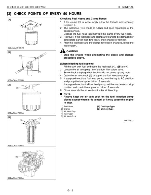
- Fuel Hose Routing and Engine Oil Drain Hose
- Accelerator Pedal and Hand Accelerator Linkages
- Engine Structure and Accessory Arrangement
- Turbocharger Specifications and Construction
- 03-M-E3B Engine Workshop Service References
- 03-M-DI-E3B Engine Workshop Service References
- 03-M-E3BG Engine Workshop Service References
- Engine Dimensions, General Information and Mechanism
- Engine Servicing Instructions
-
04. Hydraulic System — LST Pump, Motor and Steering
- Hydraulic Circuit Diagrams and Component Locations
- LST Hydraulic Pump (A4V) Construction and Operation
- Servo Cylinder and DA Regulator
- High-Pressure and Charge Relief Valves
- LST Automatic Shift and Torque Control Functions
- Pump Inclined Rotation Resetting Force and Advance Angle
- LST Pump Orifice and DA Speed Relay Valve
- DA Valve Operating Functions
- Looped Hydraulic Line Bypass
- LST System Temperature Characteristics
- LST Motor Structure and Hydraulic Circuit
- LST Motor Oil Flow and Operating Mechanism
- LST Motor Servo-Regulator
- LST System Operating Diagrams
- Hydraulic Steering Unit
- Hydraulic Troubleshooting — System Failure and Weak Lifting
- Slow Lifting and Hydraulic Cylinder Fall Diagnosis
- Forward and Reverse Travel Failure Diagnosis
- Insufficient Traction Force and Slow Travel Troubleshooting
- Starting Engine Speed Differences During Forward and Reverse Travel
- Excessive LST Brake Shock and Poor Acceleration Diagnosis
- Hydraulic Steering System Troubleshooting
- LST System, Steering and Front Loader Specifications
- Hydraulic Pressure Measurement and Testing
- Hydraulic Flow Rate Measurement
- LST Pump and Motor Removal and Installation
- LST Pump Disassembly, Repair and Servicing
- LST Motor Disassembly, Repair and Servicing
- Hydraulic Control Valve Servicing
- Steering Unit Inspection and Repair
- Hydraulic Cylinder Servicing
-
05. Brake System and Power Train
- Brake System Construction and Operating Principles
- Parking Brake Mechanism
- Axle Service Brake — EU, KCL and KTA Versions
- Negative Brake Release Mechanism
- Front Differential and Axle Shaft Assembly
- Limited-Slip Differential (LSD) Structure
- Front Axle Construction
- Rear Differential and Axle Shaft Configurations
- Rear Axle Assemblies With and Without Axle Brakes
- Negative Brake Inspection and Servicing
- Parking Valve Servicing
- Front Axle Disassembly and Assembly
- Rear Axle Disassembly and Assembly
- Limited-Slip Differential Gear Servicing
- Reduction Gear Case Assembly
- Standard Differential Assembly
- Rear Differential Axle Servicing
- Front Differential Axle Assembly
- Planetary Gear Assembly and Servicing
-
06. Electrical System and Troubleshooting
- Electrical Wiring — R420S/R420α and R520S/R520α
- Electrical Circuit Diagrams
- Electrical System Testing and Troubleshooting
- Battery Discharge and Starting System Fault Diagnosis
- Forward/Reverse Travel Selection Fault Diagnosis
- Low-Speed Hold and Automatic Levelling System Troubleshooting
- Electrical Component Specifications
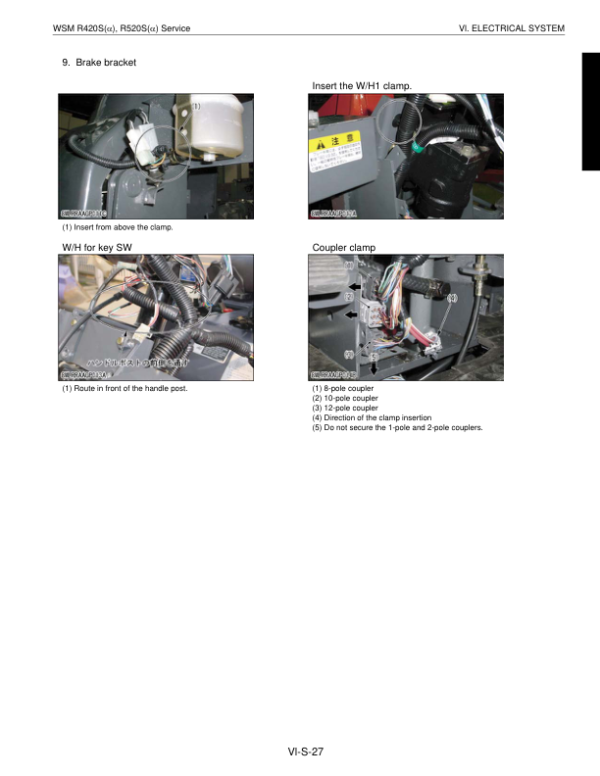
- Wiring Harness Installation Precautions and Routing
- Engine Stop Switch, Starter Switch and Glow Lamp Timer
- Indicator Lamps, Fuel Gauge and Tachometer
- Engine Water Temperature Gauge and Sensors
- Hazard, Parking, Direction Indicator and Lighting Switches
- Forward/Reverse Travel Control Switch
- Starter, F/R and Lighting Relays
- Alternator and Charging Components
- Automatic Leveller Sensor and Inverter Unit
- Automatic Levelling Control Valve and Relay
- Parking Solenoid and Engine Stop Solenoid
- Low-Speed Hold Switch and Solenoid
- Fuel Pump and Forward/Reverse Valve Solenoid
- Hydraulic Pressure and Oil Temperature Sensors
- Battery, Earth Connections, Fuse Box and Fusible Links
- Headlamps, Combination Lamps and Flasher Units
- Reverse Warning Buzzer and Back Lamp
- Cabin Electrical Relays and Power Supply
- Electrical Couplers, Connectors and Main Component Installation
-
07. Backhoe — Mechanism and Servicing
- Backhoe Hydraulic Oil Flow Chart
- Backhoe Hydraulic Circuit Diagram
- Backhoe Dimensions and Operating Specifications
- Backhoe Lifting Capacity
- Backhoe Hydraulic System Specifications
- Bucket, Boom and Arm Technical Data
- Backhoe Pin and Bushing Dimensions
- Backhoe Hydraulic Circuit Troubleshooting
- Backhoe Mechanical Structure Troubleshooting
- Backhoe Main Components and Operator Seat
- Backhoe Lubrication and Grease Fittings
- Backhoe Operating Speed Testing
- Hydraulic Cylinder Natural Fall Testing
- Main Relief and Overload Relief Pressure Testing
- Control Lever Play, Stroke and Operating Force Checks
- Bucket Sway Distance Inspection
- Bucket, Arm and Boom Removal and Reassembly
- Swing Bracket and Slide Bracket Servicing
- Swing Cylinder and Slide Lock Cylinder Removal
- Backhoe Piping Block and Control Valve Servicing
- Pilot-Operated Check Valve Servicing
- Outrigger Cylinder Removal and Reassembly
-
08. Supplement — Technical Systems and Regional Circuits
- Wheel Loader Fundamentals and Terminology
- Wheel Loader Performance Reference Data
- LST Hydraulic Drive System Introduction
- Steering System Fundamentals and Performance
- Basic Steering Hydraulic Circuit
- Orbitrol Steering Valve and Dynamic Signal System
- Direction Indicator Priority Circuits — KTC, KCL and KTA
- Hazard Warning Priority Circuit — EU Version
- Glow Plug and Starter Electrical Circuit Functions
- Forward and Reverse Travel Control Circuit Operation
- Engine Oil Pressure Warning Circuit
- Automatic Leveller Electrical Circuit
- R420S/R420α and R520S/R520α Circuit Comparisons
- Regional Wiring and Electrical Circuit Diagrams
- Hydraulic Circuits — North America and Oceania Versions
- Hydraulic Circuits — European Versions
- Regional Hydraulic Component Layouts
- Backhoe Hydraulic Circuit References
- 09. Conversion Tables
LST Drive System, Regional Configurations and Backhoe Servicing
The hydraulic documentation provides detailed coverage of the LST drive system, including A4V pump control, automatic shifting, torque regulation, hydraulic motor operation and pressure/flow testing. Its troubleshooting procedures distinguish lifting faults from forward/reverse travel problems, insufficient traction, abnormal starting engine speed and excessive braking shock. The Brake System and Power Train chapter complements these references with negative brake servicing, differential assemblies and planetary reduction components.
The machine-body and electrical sections distinguish regional configurations and model-change arrangements. The supplement provides separate wiring and hydraulic diagrams for North American, Oceania and European versions, together with direction-indicator and hazard-priority circuit differences. The Backhoe chapter includes its own hydraulic schematics, operating performance tests and servicing references for the boom, arm, bucket, swing and stabilizing components.
The product also lists a separate 322-page service-repair document alongside the 820-page workshop publication. The Table of Contents above reflects the indexed workshop material; consult each document’s individual listing to determine its applicable model coverage and included service information.




























Reviews
There are no reviews yet.