Overview
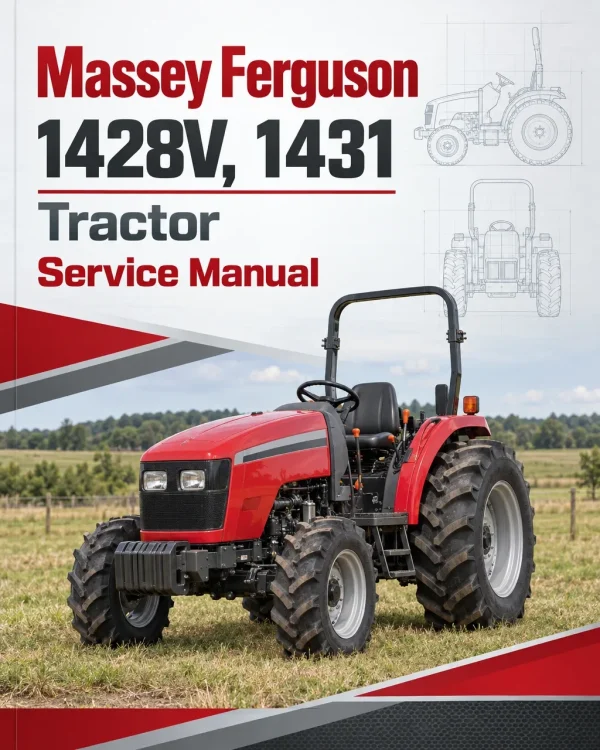
The Massey Ferguson 1428V and 1431 Hydro Compact Tractor Service Manual provides technical information for servicing, maintaining and repairing these compact agricultural tractors. It includes component identification, disassembly and reassembly procedures, inspection guidelines, hydraulic system specifications and electrical troubleshooting references for workshop maintenance.
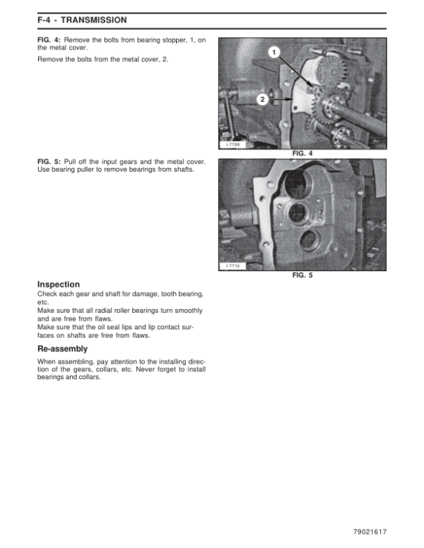
Coverage includes tractor separation and major component removal, engine accessories, transmission servicing, hydrostatic drive components, front axle assemblies, hydraulic steering and electrical equipment. The hydrostatic transmission section addresses internal component inspection, reassembly and pressure testing, while the hydraulic and steering chapters provide information on control valves, gear pumps, circuit operation and system troubleshooting.
Notice: The supplied bookmarks identify this as a Hydro Compact Tractor Service Manual. Some sections named in the previous product description, including a standalone clutch chapter, rear transmission chapter and lubrication chapter, are not separately identified in the uploaded bookmark index. Check the complete manual when confirming coverage of those systems.
Table of Contents
Massey Ferguson 1428V, 1431 Manual
- 01. General Information
- 02. Splitting the Tractor
- Disassembly of Function Blocks
- Exterior Parts
- Hood and Front Grille
- Seat, Fenders, Floor Deck and Related Parts
- Removal of Exterior Parts as a Set
- Radiator
- Separation of Engine from Front Transmission
- Removal of Engine
- Separation of Front Transmission Case from Middle Transmission Case
- Separation of Middle Transmission Case from Rear Transmission Case
- Separation of Rear Axle Housing from Rear Transmission Case
- Removal of Cylinder Case
- Removal of Front Axle
- Removal of Power Steering Unit
- 03A. Engine Accessories
- 03B. Engine
- 04. Transmission
- 05. Hydrostatic Transmission
- Required Tools
- Construction and Names of Major Components
- Criteria for Replacing Worn Parts
- Reassembly
- Parts List
- Hydrostat Testing Procedure
- 06. Front Axle
- 07. Steering
- Construction
- Steering Hydraulic Circuit
- Integral Orbit Roll
- Disassembly
- Inspection
- Reassembly
- Troubleshooting
- 08. Hydraulic System
- General Description
- Specifications
- Major Components of Hydraulic System
- Main Control Valve
- Flow Control Valve
- Safety Valve
- Relief Valve
- Gear Pump
- Troubleshooting
- 09. Electrical System
- Electrical Formulas
- General
- Battery
- Instrument Panel
- Fuel Gauge and Sensor
- Turn / Hazard Lights Switch
- PTO Switch
- Light Switch
- Glow Indicator
- Engine Glow Plugs
- Instrument Light Bulbs
- PTO Safety Relay
- Cable Layout
- Wiring Harness Layout
- Safety Circuit Wiring Diagram
- Troubleshooting
Hydrostatic Transmission Inspection and Pressure Testing
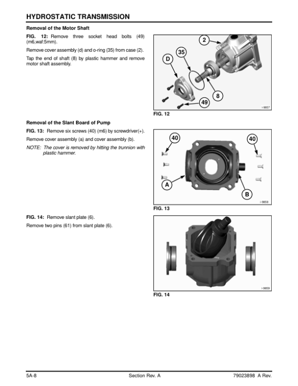
The hydrostatic transmission documentation identifies the major internal components and provides procedures for disassembly, inspection and reassembly of the hydrostat unit. Technical references include pump and motor components, shaft assemblies, the port block, criteria for replacing worn parts and hydrostatic transmission testing. The testing procedures specifically address charge pressure and high-pressure relief checks.
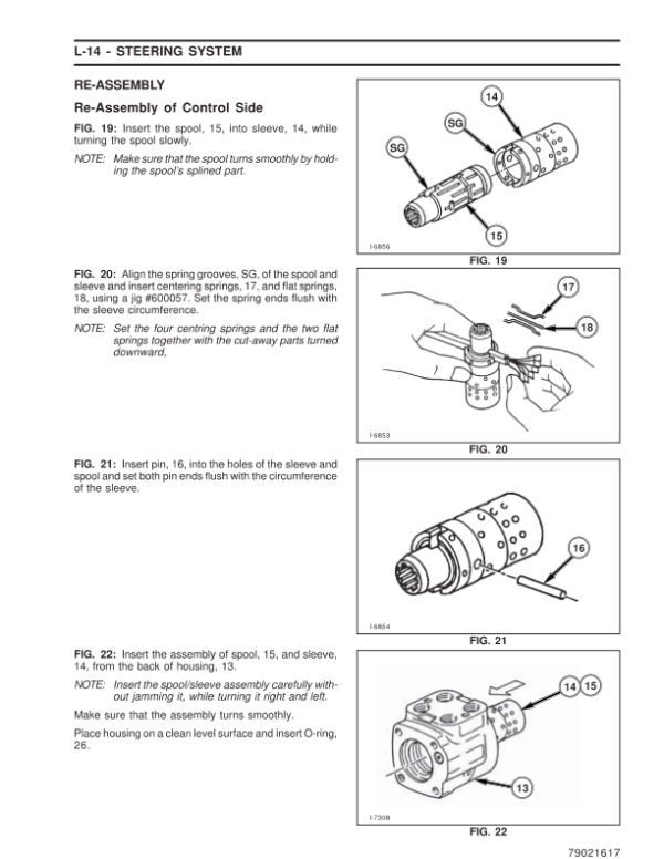
For hydraulic servicing, the manual includes system specifications, control valve operation, flow control and relief valves, gear pump inspection and troubleshooting. The steering section covers the hydraulic circuit, integral orbit roll construction, disassembly, inspection and reassembly. Electrical references address the charging and starting-related components, gauges, switches, wiring harnesses and safety circuit diagnostics.





















Reviews
There are no reviews yet.