Overview
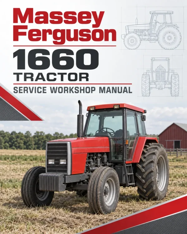
The Massey Ferguson 1660 Compact Tractor Workshop Service Repair Manual provides detailed technical information for maintaining, troubleshooting, servicing and repairing the Massey Ferguson MF 1660 agricultural tractor. This workshop manual covers engine specifications and overhaul procedures, major component removal, clutch assemblies, Power Shuttle and Quadra Shift transmission systems, front and rear axles, braking systems, hydraulic equipment, electrical components, hydrostatic steering and cab air conditioning.
Workshop coverage includes diesel engine disassembly and reassembly, fuel injection pump servicing, transmission clutch packs, gear shifting mechanisms, differential and final drive repairs, independent and mid PTO components, hydraulic pumps and control valves, electrical wiring diagrams and digital instrument diagnostics. Additional sections provide hydraulic schematics, transmission sensor adjustments, CT diagnostic software instructions, Orbitrol steering repairs, air-conditioning maintenance, tightening specifications and component troubleshooting procedures.
Important Information: The documentation includes Power Shuttle and Power Shift (Quadra Shift) transmission arrangements, as well as platform and cab configurations. Some equipment, including the mid PTO, front-loader hydraulic controls and air conditioning, is configuration-specific. Verify the tractor’s installed components before following a service procedure.
Table of Contents
Massey Ferguson 1660 Compact Tractor Workshop Service Manual
-
01. General Information
- General Introduction
- Tractor Identification and Model/Serial Numbers
- Replacement Parts Information
- Units of Measurement
- Tractor Specifications and Capacities
- Engine Specifications
- Transmission Specifications
- Power Take-Off (PTO) Specifications
- Hydraulic System Specifications
- Electrical System Specifications
- Fluid Capacities and Maximum Load Capacity
- General Tractor Dimensions
- Lubrication and Fill Points
- Periodic Inspection and Maintenance Chart
- General Precautions for Disassembly and Installation
- Bearings, Oil Seals, O-Rings and Standardized Parts
- Tightening Torque Chart
- Conversion Tables
-
02. Engine
- Cooling System
- Radiator, Fan Belt and Thermostat
- Radiator Reserve Tank System
- Fuel System
- Fuel Filter and Fuel Pump
- Fuel System Air-Bleeding Procedure
- Throttle Lever
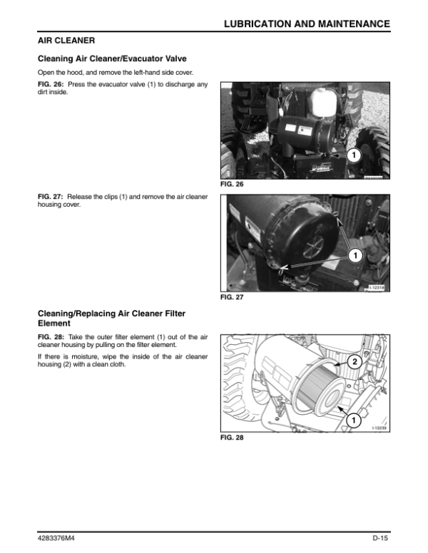
- Air System and Engine Air Cleaner
- Engine General Information and Specifications
- Engine Service Standards
- Engine Troubleshooting
- Dimensional Specifications and Tightening Torques
- Engine Inspection and Service Procedures
- Engine Oil and Oil Filter Replacement
- Fan Belt Tension and Coolant Inspection
- Cylinder Head Inspection and Repair
- Valve Seats, Valve Guides and Valve Springs
- Rocker Arm Shaft and Cylinder Head Gasket
- Cylinder Block, Pistons and Connecting Rods
- Crankshaft Inspection
- Intake and Exhaust Valve Mechanism
- Valve Timing and Valve Clearance Adjustment
- Camshaft Inspection
- Engine Disassembly
- Engine Reassembly
- Crankshaft, Pistons and Connecting Rod Installation
- Timing Gears, Gear Case and Flywheel Installation
- Engine Lubrication System
- Oil Pump, Oil Filter and Relief Valve
- Coolant System and Water Pump
- Thermostat Inspection and Fan Belt Adjustment
- Fuel Injection System
- Fuel Injection Pump Construction and Operation
- Injection Pump Timing and Adjustment
- Injection Pump Removal, Inspection and Assembly
- Injection Volume Adjustment
- Injection Nozzle and Nozzle Holder
- Fuel Governor Construction and Operation
- Alternator Specifications and Construction
- Alternator Removal, Inspection and Assembly
- Alternator Charging Troubleshooting
- Glow Plugs – Construction and Inspection
- Tachometer Speed Pick-Up
- Starter Motor Construction and Servicing
- Starter Motor Inspection and Performance Testing
-
03. Major Components
- Major Component Disassembly and Assembly Chart
- Service Access Procedures
- Hood and Side Cover Removal
- Front Axle Removal and Installation
- Engine Separation from Clutch Housing
- Engine Separation from Front Transmission
- Engine Removal
- Clutch Housing and Front Transmission Separation
- Front and Rear Transmission Case Separation
- Lift Cylinder Case Removal
- Rear Axle Separation from Rear Transmission Case
- Platform Removal
- Cab Removal
- Cab Roof Removal and Installation
- Fuel Tank Removal
- Radiator Removal
- Chassis Components
- Fenders, Floor Mats and Steps
- Hood, Seat and Console
- Instrument Panel
- ROPS Frame
- Steering Column and Steering Wheel
- Three-Point Linkage
- Drawbar and Related Components
-
04. Clutch
- Clutch Construction and Specifications
- Clutch Components
- Clutch Removal
- Clutch Disassembly and Assembly
- Clutch Pedal Adjustment
- Release Bearing – Removal and Inspection
- Release Bearing Assembly
- Clutch Cross Shaft
- Clutch Cross Shaft Removal and Installation
- Clutch Free-Play Adjustment
- Synchro Shuttle and Power Shuttle Clutch Adjustment
- Clutch Housing Plug Removal
- Clutch Troubleshooting
-
05. Transmission
- Transmission General Information
- Power Shuttle Transmission
- Power Shift (Quadra Shift) Transmission
- Power Train and Gear Ratios
- Shuttle Clutch
- Power Shuttle Clutch Pack
- Reverse Clutch Disassembly
- Input Gears
- Input Gear Disassembly and Reassembly
- Input Housing
- Transmission Main Change Gears
- Main Shift and Shift Fork Assembly
- Main Shift Lever
- Quadra Shift Transmission
- Power Shift Components and Design
- Power Shift Hydraulic Circuit
- Power Shift Electrical Wiring Circuit
- Quadra Shift Component Locations and Functions
- Power Shuttle Valve
- Gear Shift Change Piston
- Power Shuttle Operation
- Quadra Shift Operation
- Speed Change Pistons
- Shift Position Sensors
- Shift Position Sensor Errors
- Clutch Boost Pressure Control
- Power Shuttle Lever Operating Patterns
- Gear Shift Button Operation
- Transmission Range Change Gears
- Range Shift Linkage and Range Lever
- Independent Power Take-Off (PTO)
- PTO Clutch
- Mid Power Take-Off
- Mid-PTO Linkage
- Four-Wheel-Drive Gears
- 4WD Shift Mechanism
-
06. Rear Axle and Brakes
- Rear Axle and Brake System – General Information
- Rear Axle Housing and Differential Gears
- Rear Axle Housing Disassembly
- Ring Gear and Pinion
- Ring Gear and Pinion Removal and Installation
- Ring Gear and Pinion Overhaul
- Ring Gear and Pinion Inspection
- Ring Gear and Pinion Reassembly
- Brake System
- Brake Disassembly, Inspection and Adjustment
- Parking Brake Lever Adjustment
- Differential
- Differential Lock
- Rear Axle and Brake Troubleshooting
-
07. Front Axle
- Front Axle Construction
- Front Axle Specifications
- Front Wheel Drive Shaft
- Front Wheel Drive Shaft Removal and Installation
- Front Wheel Drive Shaft Inspection and Assembly
- Front Differential
- Pinion Carrier Assembly Removal and Installation
- Front Differential Overhaul
- Differential Gear Disassembly and Inspection
- Differential Gear Reassembly
- Final Drive and Wheel Shaft
- Wheel Shaft Oil Seal and Cover
- Front Axle Centre Section
- Front Axle Bracket Oil Seal
- Final Drive Housing Overhaul
- Final Drive Housing Inspection and Assembly
- Front Wheel Alignment
- Toe-In Adjustment
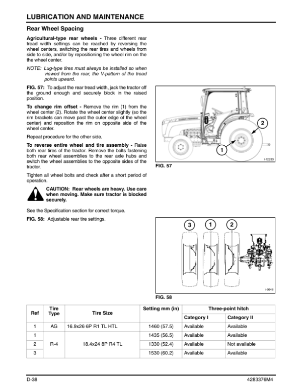
- Wheel Spacing
- Steering Free-Play
- Front Axle Troubleshooting
-
08. Hydraulic System
- Hydraulic Circuit and Schematic Diagrams
- Power Shuttle Transmission Hydraulic Circuit
- Q-Type Transmission Hydraulic Circuit
- Hydraulic System Specifications
- General Hydraulic Service Procedures
- Transmission and Hydraulic Oil Level Inspection
- Transmission Oil Replacement
- Hydraulic Oil Filter Replacement
- Hydraulic Major Components and Locations
- Hydraulic Suction Filter
- Hydraulic Gear Pumps – Main Pump and Sub Pump
- Power Steering Cylinder
- Transmission Oil Cooler and Main Clutch Lubrication
- Main Hydraulic Cylinder
- Main Relief Valve
- Steering Orbitrol Hydraulic Circuit
- Slow Return Valve
- Hydraulic Safety Valve
- PTO Control Valve
- Pressure-Reducing Valve
- Main Hydraulic Control Valve
- Gear Shifting Valve
- Joystick Control Valve
- Front Loader Boom Control Valve
- Front Loader Bucket Control Valve
- Front Loader Hydraulic Adapter
- External Auxiliary Hydraulics
- Remote Hydraulic Control Valve Overhaul
- Auxiliary Hydraulic Outlets
- Auxiliary Hydraulic Pressure Release
- Hydraulic Control Linkage
- External Auxiliary Hydraulic Control Lever
- Joystick Linkage and Operating Positions
- Position Control Linkage and Adjustment
- Draft Control Linkage and Adjustment
- Three-Point Lift Linkage
- Three-Point Hitch Specifications
- Drawbar Components
- Hydraulic System Troubleshooting
-
09. Electrical System and Diagnostics
- Electrical Wiring Diagrams and Colour Chart
- Platform Tractor – Power Shuttle Wiring Diagrams
- Cab Tractor – DynaQPS Wiring Diagrams
- Solenoid Valves
- PTO Solenoid Valve
- Power Shuttle Solenoid Valve
- Solenoid Valve Resistance Testing
- Digital Dashboard Panel
- Digital Dashboard Warning Indicators
- Shuttle Lever and Range Lever Warnings
- Service Interval and Programming Error Indicators
- Coolant Temperature and Oil Pressure Warnings
- Transmission Shift Malfunction Indicators
- Digital Instrument Panel Switches and Sensors
- Digital Panel Programming
- Changing Display Language
- Changing Tyre Size Settings
- Checking and Clearing Error History
- Digital Panel Wiring Harness
- Standard Instrument Panel
- Electrical Switches and Relays
- Main Wiring Harness
- Power Shuttle Controls
- Power Shuttle Valve
- PTO Electrical Controls
- CT Diagnostics User Guide
- Diagnostic Software Installation and Configuration
- Connecting Diagnostic Software to the Tractor
- IQ Shift Diagnostic Operation
- IQ Shift Input and Output Data
- Transmission Shift Position Sensor Settings
- Gear Shift Controller Adjustments
- Clutch Engagement Pressure Adjustment
- Forward and Reverse Clutch Pressure Settings
- IQ Shift Neutral Waiting Time Settings
- PTO Diagnostic Operation
- PTO Input and Output Data
- PTO Clutch Engagement Pressure Settings
- Digital Panel Diagnostic Operation
- Diagnostic Software Communication Settings
- Diagnostic Troubleshooting
- Signal Converter and Serial Cable Specifications
-
10. Hydrostatic Steering
- Hydrostatic Steering General Information
- Steering Unit Construction
- Major Steering Components
- Integral Orbitrol Steering Unit
- Steering Unit Disassembly
- Disassembly of Rotor Side
- Disassembly of Control Side
- Steering Component Inspection
- Steering Unit Reassembly
- Assembly of Control Side
- Assembly of Gerotor Side
- Flow Control Valve Assembly
- Hydrostatic Steering Troubleshooting
-
11. Cab and Air Conditioning
- Cab and Air Conditioner – General Information
- Cab Roof
- Cab Door
- Cab Door Opening Angle Adjustment
- Door Lock
- Cab Glass Bonding
- Cab Electrical Equipment
- Air-Conditioning Dual Pressure Switch
- Cab Wiring Harness
- Air-Conditioning Pipes and Hoses
- Heater Hoses and Drain Hoses
- Rear-View Mirror Adjustment
- Cab Insulation Installation
- Air-Conditioning Major Components and Specifications
- Air-Conditioning System Construction and Operation
- Compressor Assembly
- Compressor Magnetic Clutch
- Air-Conditioning Safety Relief Valve
- Condenser
- Receiver Dryer and Desiccant
- Air-Conditioning Unit
- Expansion Valve
- Pressure Switch and Thermostat
- Air-Conditioning Control and Operation
- Air-Conditioning Inspection and Maintenance
- Refrigerant Level Inspection
- Air-Conditioner Belt Inspection and Adjustment
- Condenser Cleaning and Inspection
- Air-Conditioning Hose and Pipe Inspection
- Air-Conditioner Filter Maintenance
- Compressor and Receiver Dryer Servicing
- Air-Conditioning Control Cable
- Air-Conditioning Component Assembly
- Compressor Lubricating Oil and Oil Level
- Refrigerant Charging Procedures
- Air Evacuation and Leak Testing
- Service Gauge Manifold Connection
- High-Pressure and Low-Pressure Refrigerant Charging
- Air-Conditioning Troubleshooting
- Service Gauge Manifold Diagnostics
Transmission, Hydraulic and Electrical Service Information
The Massey Ferguson 1660 workshop manual includes technical procedures for engine overhaul, Power Shuttle and Quadra Shift transmission repairs, PTO clutch servicing, front and rear axle maintenance, hydraulic pump and control valve servicing, and Orbitrol steering repairs. Electrical wiring diagrams, digital instrument diagnostics, CT diagnostic software instructions and cab air-conditioning references support troubleshooting and workshop repairs on compatible tractor configurations.





















Reviews
There are no reviews yet.