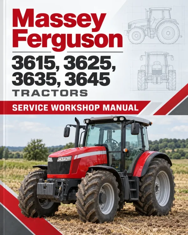
Massey Ferguson 3615, 3625, 3635, 3645 Tractors Workshop Service Manual

$42.00

What’s Included

Workshop Service Manual 851 Pages
Operator Manual 185 Pages
Engine Manual 44 Pages

Technical Details

Brand Massey Ferguson
Models Covered 3615, 3625, 3635, 3645
Machine Type Tractor
Documentation Workshop Manual, Operating Manual & Engine Manual
Publication Number 4283084M2, VA208233, 836662470,
Language English
Format PDF
SKU: 554642 Category:
Guaranteed Safe Checkout

‘

Overview

The Massey Ferguson 3615, 3625, 3635 and 3645 Tractor Workshop Service Repair Manual provides technical information for servicing, maintaining, diagnosing and repairing these Massey Ferguson agricultural tractors. The documentation includes tractor specifications, component identification, assembly and disassembly procedures, transmission servicing, differential repairs, axle maintenance, hydraulic system adjustments and electrical troubleshooting references.

The workshop manual covers the 506 HTR transmission, including 8+8, 12+12 and 24+24 transmission configurations with Synchro Shuttle, Power Shuttle and splitter arrangements. Detailed procedures address clutch assemblies, transmission shafts, synchronisers, final drives, power take-off components, braking mechanisms and differential equipment. Separate technical sections cover two-wheel-drive axle components, steering adjustments and hydraulic system servicing.

Additional references include tractor dimensions, identification information, lubrication specifications, electrical diagrams, hydraulic lift system operation, control valve adjustments and component removal procedures. An amendment section provides updated Power Shuttle testing information, electrical wiring diagrams and fault codes for different tractor production configurations.

Safety: The documentation includes an Introduction and Safety section together with servicing precautions for major mechanical assemblies. Review the appropriate procedures before working on pressurised hydraulic systems, transmission components, brakes or supported tractor assemblies.

Notice: The manual documents several transmission arrangements and includes electrical and Power Shuttle amendments distinguished by tractor serial number. In particular, the amendment identifies configurations before and from serial number CS20011 and separate COM2/Tier 2 and COM3/Tier 3 engine wiring references. Verify the tractor’s identification and installed components before selecting a procedure.

Table of Contents

Massey Ferguson 3615, 3625, 3635, 3645 Manual

  • 01. Introduction and Safety
  • 02. General Information, Specifications, Assembly and Disassembly

    • Manual Use
    • Agreements and Definitions
    • General Description and Workshop Repair Information
    • Product Identification
    • Tractor Dimensions and Weights
    • Steering Angle
    • Steering Radius
    • Travel Speed
    • Tyres and Tyre Pressure
    • Battery – Description, Maintenance and Testing
    • Alternator – General Maintenance
    • Air Filter – Disassembly and Assembly
    • Air Filter Line – Disassembly and Assembly
    • Battery – Removal and Installation
    • Alternator – Removal and Installation
    • Radiator – Disassembly and Assembly
    • Fan – Disassembly and Assembly
    • Exhaust Pipe
    • Fan Belt
    • Air Filter Assembly Replacement
    • Hood
    • Front Weight
    • Oil Cooler
    • Muffler
    • Hydraulic Pump
    • Starting Motor
    • Engine Removal
    • Two-Wheel-Drive Front Axle
    • Fuel Tank
    • Brake Cylinder
    • Hand Brake Adjustment
    • Lock Valve
    • Rockshaft Valve
    • Rear Wheels
    • Auxiliary Distributors
    • Oil Suction Strainer
    • Oil Filter Cartridge Replacement
    • Side Auxiliary Distributors
    • Power Shuttle Hydraulic Valve
    • Oil Filter Sensor
    • Clutch Box
    • Rockshaft
    • Platform
    • Steering Valve
    • Brake Circuit Bleeding
    • Electrical Diagrams
    • Beacon Light Wiring
    • North American Right Turn Signal Light Wiring
    • North American Left Turn Signal Light Wiring
    • Cab Rear Beam Wiring
    • Alternator Cable
    • Battery Positive and Negative Connections
    • Ground Connector
    • Licence Plate Light Extension
    • Beam Wiring Extension
    • PTO 540 Connector
    • North American Cab Front Beam Wiring
    • Cab Swinging Beam Extension
    • Hydraulic System Components
    • Troubleshooting
    • Axle Problems and Diagnosis
    • Hydraulic Lift Specifications
    • Hydraulic Circuit Diagram
    • Hydraulic Lifting Device Circuit Diagram
    • Control Valve Operation
    • Internal Linkage System Operation
    • Use of Control Levers
    • Control Valve Sensitivity Adjustment
    • Position Control Lever Adjustment
    • Draft Control Lever Adjustment
    • Reaction Spring Assembly Inspection
    • Push Rod Measurement
    • Hydraulic System Diagnosis
  • 03. Differential

    • Differential Assembly – Disassembly and Assembly
  • 04B. Transmission – 506 HTR

    • Manual Use
    • Information Property
    • Agreements and Definitions
    • General Description
    • Recommendations for Repair Operations
    • Intended Use
    • Transmission Product Identification
    • Technical Features – Synchro Shuttle, Power Shuttle and Splitter Configurations
    • Tightening Torques, Sealants and Grease Application
    • Hi/Lo Power Flow Diagrams
    • Typical Assembly Data
    • Filling and Checks
    • Service Schedule
    • Hydraulic System Assembly
    • Drop Box
    • Final Drive – 55 to 75 HP
    • Final Drive – 85 HP
    • Teflon Seal Replacement – Clutch Shaft
    • Input Shaft and Support
    • Upper Covers and Rockshaft
    • Speed and Range Levers
    • Clutch Housing – Synchro Shuttle
    • Clutch Housing – Synchro Splitter
    • Synchro Shuttle and Power Splitter
    • Power Shuttle and Synchro Splitter
    • Air Compressor
    • Wet Clutch – Power Splitter
    • Wet Clutch – Power Shuttle
    • Hi/Lo Synchroniser – Synchro Splitter
    • Cover and PTO Wet Clutch
    • Power Take-Off
    • PTO Input Shaft
    • PTO Output Shaft
    • PTO Brake
    • Ground Drive PTO
    • Slave Cylinder
    • Parking Brake
    • Housing Sensor Assembly
    • Differential Locking Control
    • Inner Control Assembly
    • Idler Gear
    • Power Shuttle
    • Range Gears – Primary Shaft
    • Input Shaft – Synchro Shuttle
    • Input Shaft – 12+12 Power Shuttle
    • Shuttle Synchroniser Replacement
    • Speed Gears – Primary Shaft
    • Differential Assembly
    • Range Pinion – Secondary Shaft
    • Secondary Shaft
    • Speed Gears – Secondary Shaft
    • Special Tools
  • 05A. Two-Wheel-Drive Front Axle

    • Manual Use
    • Information Property
    • Agreements and Definitions
    • General Description
    • Recommendations for Repair Operations
    • Intended Use
    • Axle Product Identification
    • Technical Features
    • Maintenance
    • Grease Application During Assembly
    • Adhesives and Sealants
    • Tightening Torques
    • Steering Cylinder Group
    • Wheel Hub Group
    • Wheel Hub Support Group
    • Axle Beam Group
    • Toe-In and Steering Angle Adjustment
    • Troubleshooting
    • Axle Problems and Diagnosis
    • Special Tools
    • Service Operations Time Schedule
  • 05G. Front Axle
  • 06. Engine – Sisu Fortius Series
  • 07. Amendment

    • 07A. Electrical Diagrams
    • 07B. Power Shuttle Testing
    • 07C. Fault Codes and Messages

506 HTR Transmission, Synchro Shuttle and Power Shuttle Servicing

The 506 HTR transmission documentation provides technical information for multiple drivetrain configurations, including 8+8 Synchro Shuttle, 12+12 Synchro Shuttle, 24+24 Synchro Shuttle with Synchro Splitter, 24+24 Synchro Shuttle with Power Splitter, 12+12 Power Shuttle and 24+24 Power Shuttle with Synchro Splitter arrangements. It includes transmission identification, mechanical operating principles, power flow diagrams, lubrication references, assembly measurements and component servicing procedures.

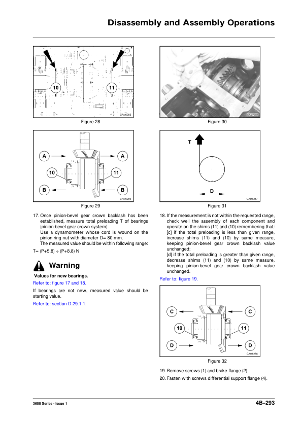
Detailed repair sections address wet clutch assemblies, Power Shuttle and Power Splitter components, transmission input shafts, primary and secondary shafts, range gears, synchronisers, clutch housings, final drives and PTO mechanisms. Additional references include clutch pack wear inspection, bearing preload adjustments, hydraulic valve servicing, differential locking mechanisms and parking brake components.

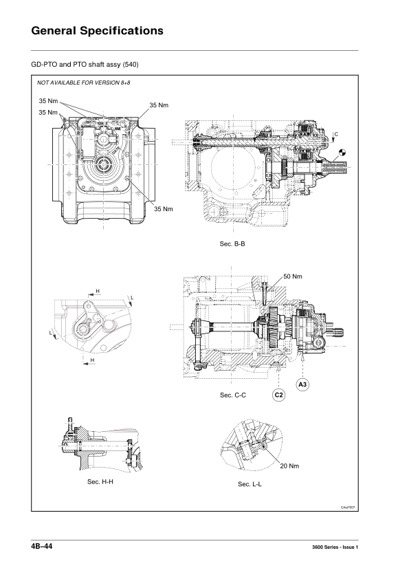
The transmission also contains separate servicing information for PTO wet clutches, PTO input and output shafts, PTO braking and ground drive PTO equipment. Technicians should identify the transmission version and PTO arrangement before selecting the appropriate disassembly, reassembly or adjustment procedure.

Differential, Front Axle and Steering Repair Information

The differential chapter provides assembly and disassembly procedures, while the transmission documentation contains additional differential servicing references. The two-wheel-drive front axle chapter covers steering cylinders, wheel hubs, hub supports, axle beams and steering geometry adjustments.

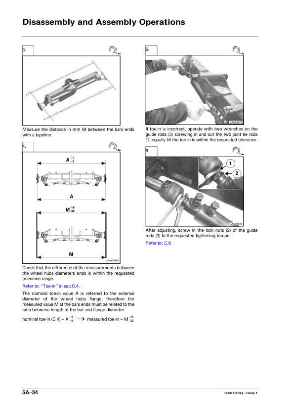
Technical information includes axle identification, maintenance, lubrication, tightening torques, toe-in adjustments, steering angle settings and troubleshooting. A separate Front Axle chapter is also identified in the workshop documentation. Select the applicable axle information according to the tractor’s configuration.

Hydraulic System Operation and Control Valve Adjustments

The general workshop information includes hydraulic system components, rockshaft valve servicing, hydraulic pump removal and installation, auxiliary distributors, Power Shuttle hydraulic valves and hydraulic oil filtering components.

The hydraulic lifting system references describe control valve operation, internal linkage mechanisms, position control, draft control and combined position/draft operation. Additional procedures address control valve sensitivity, position lever and draft lever adjustments, reaction spring inspection, push rod measurements and hydraulic troubleshooting.

Power Shuttle Electrical Diagrams and Serial Number Amendments

The amendment includes additional electrical wiring diagrams and Power Shuttle testing procedures. It identifies Power Shuttle EHM 24 systems used before serial number CS20011, a Trax 56-pin conversion kit for earlier tractors, and Trax 56-pin production wiring effective from serial number CS20011.

Other electrical references distinguish COM2/Tier 2 and COM3/Tier 3 engine configurations, including North American platform wiring. The Power Shuttle amendment contains hydraulic flow information, testing specifications and clutch pressure-testing procedures. Separate fault-code references are provided for tractors manufactured before serial number CS20011 and those equipped with TRAX 56-pin EHM equipment.

Use the tractor’s serial number and installed electronic control components when selecting the appropriate wiring diagram or fault-code information. This distinction is particularly important when diagnosing Power Shuttle operation or servicing tractors with updated electrical equipment.


Reviews

There are no reviews yet.

Only logged in customers who have purchased this product may leave a review.

Massey Ferguson 3615, 3625, 3635, 3645 Tractors Service Workshop Manual
Massey Ferguson 3615, 3625, 3635, 3645 Tractors Workshop Service Manual

$42.00

Add to cart