Overview
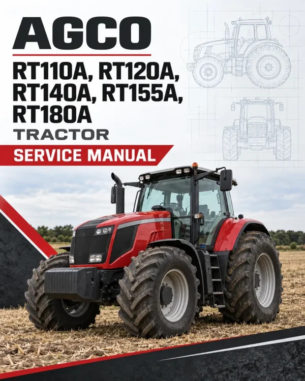
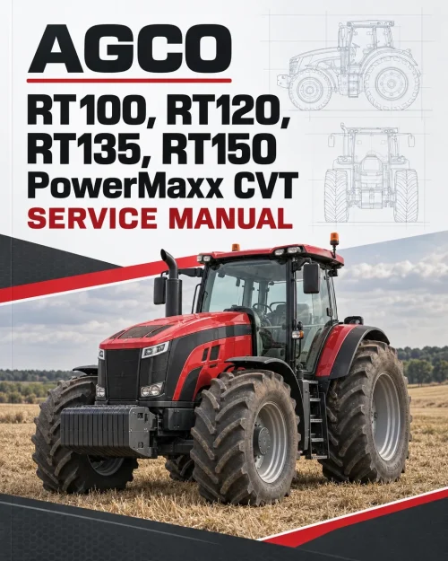
The AGCO RT110A, RT120A, RT140A, RT155A, and RT180A Tractor Workshop Service Manual provides detailed technical information for tractor maintenance, troubleshooting, inspection, and component repair. The documentation covers engine servicing, mechanical and PowerMaxx transmissions, rear and front axles, power take-off, hydraulic systems, electrical equipment, and electronic control systems.
The workshop documentation includes component removal and refitting procedures, transmission disassembly and reassembly, hydraulic circuit testing, brake servicing, electrical wiring diagrams, diagnostic fault codes, and electronic controller calibration. Standard and PowerMaxx service references provide technical specifications, system descriptions, and illustrated procedures for servicing the applicable tractor configurations.
Table of Contents
AGCO RT110A, RT120A, RT140A, RT155A, RT180A Manual
- Introduction and Specifications
- General tractor specifications
- Ground speeds and general dimensions
- Fluid capacities and conversion tables
- Locking compounds and sealants
- Tightening torque specifications
- Engine
- Engine general information
- Engine specifications and characteristics
- Fuel, oil, and coolant requirements
- Gearbox
- PowerMaxx transmission operation
- Transmission operating diagrams
- PowerMaxx hydraulic system
- Forward and reverse high-pressure relief valves
- Scavenging valve and control spool valve
- Transmission hydraulic testing
- PowerMaxx transmission unit replacement
- Transmission disassembly and reassembly
- Gearbox filling procedures
- Rear Axle
- Rear axle final drive units
- Final drive removal and refitting
- Rear axle braking system
- Rear brake removal and installation
- Wheel brake cylinder servicing
- Rear differential and drive pinion
- Differential removal and reassembly
- Drive pinion disassembly and refitting
- Power Take-Off
- Rear PTO system
- Power take-off drive transmission
- PTO clutch and transmission shaftline
- Front Axle
- Front axle construction and specifications
- Carraro final drive units
- Steering ram and wheel hub servicing
- Epicyclic drive unit disassembly and reassembly
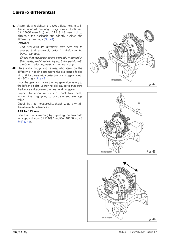
- Carraro differential servicing
- Front axle bearings and transmission shafts
- Four-wheel-drive clutch operation and servicing
- Universal joint shaft brake
- Carraro axle suspension
- Wheel alignment and steering lock adjustment
- Front axle troubleshooting
- Hydraulics
- Hydraulic circuit description and specifications
- Transmission and auxiliary hydraulic diagrams
- Auxiliary Load Sensing spool valves
- Electrohydraulic spool valve servicing
- Hydraulic control cable adjustments
- Load Sensing lift control valve
- Hydraulic distribution block servicing
- Load Sensing hydrostatic steering
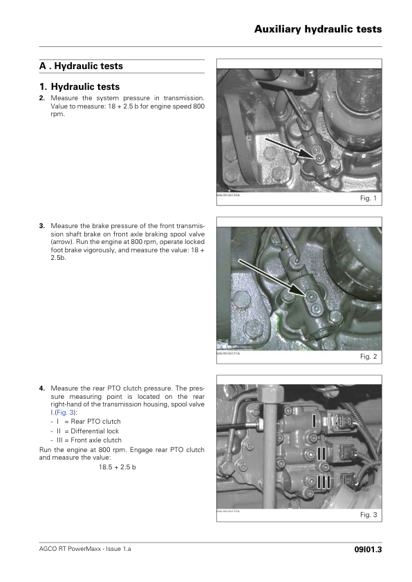
- Auxiliary hydraulic system testing
- Hydraulic pressure test ports
- Electrical Equipment
- Fuse box identification
- Cab electrical wiring diagrams
- Engine electrical equipment
- Lighting system diagrams
- Additional electrical circuits
- Electronics
- DCC2 PowerMaxx CVT programming
- DCC2 fault codes and diagnostics
- Transmission controller calibration and constants
- Autotronic 4 electronic control system
- Autotronic 4 programming and parameter settings
- Autotronic 4 tests and diagnostics
- Autotronic 4 fault codes and calibration
- Electronic linkage control and adjustments
- Linkage diagnostics and error codes
- Datatronic 2 programming and calibration
- Datatronic 2 diagnostics and fault codes
- SMS joystick programming and troubleshooting
- Joystick calibration and adjustments
- Electronic system wiring diagrams
- Cab and Equipment
- Suspended cab operation
- Cab suspension pneumatic system
- Cab suspension control components
- Air conditioning system specifications
- Standard and automatic air conditioning
- Air conditioning maintenance and troubleshooting
- Air conditioning electrical diagrams
- Refrigerant circuit draining and leak inspection
- Air conditioning refilling and pressure testing
Power Take-Off Drive and Transmission Kinematics
The power take-off system transmits engine rotation to the rear PTO clutch located at the front of the centre housing. The documented drive arrangements include the Power Shuttle, four-speed Powershift, and GTA1040 transmission gearbox configuration, as well as the Powershift, Power Shuttle, and GTA1540 transmission gearbox configuration.
The intermediate shaft is splined to the layshaft and drives the applicable transmission gears according to the position of the couplers. When a selected gear transfers rotation to the lower shaftline, the remaining gears rotate freely on their respective axes. Understanding these drive arrangements helps identify the transmission components involved in power delivery to the rear PTO.

















Reviews
There are no reviews yet.