Overview
The Kubota BX23S, LA340 and BT603 Tractor Loader Backhoe Workshop Service Manual provides technical documentation for maintenance, inspection, troubleshooting and component repair of the BX23S tractor, LA340 front loader and BT603 backhoe. The workshop reference covers safety instructions, equipment identification, engine systems, hydrostatic transmission (HST), front axle, steering, hydraulics, electrical equipment, mower assemblies, loader components and backhoe mechanisms. Separate technical sections explain component construction, operating principles, inspection, adjustment, disassembly and servicing procedures.
The documentation includes engine overhaul and fuel-system testing, HST pressure adjustments, PTO clutch servicing, differential inspection, hydraulic pump testing, loader control-valve operation and backhoe hydraulic circuits. The Front Loader chapter addresses quick-attachment mechanisms, hydraulic couplers, boom and bucket cylinders and optional third-function controls. The Backhoe chapter covers control-valve operation, stabilizers, boom and dipperstick assemblies, hydraulic cylinder servicing and component wear inspection. Additional mower references include RCK-series deck installation, cutting-height adjustment and gearbox servicing.
Safety: Review the tractor, mower, loader and backhoe safety instructions before performing workshop operations. The documentation identifies precautions for high-pressure hydraulic fluid, hot exhaust components, battery handling, workshop ventilation and equipment servicing. Follow the applicable safety procedures when removing attachments, disassembling hydraulic cylinders or working on drivetrain components.
Important Information: The workshop documentation includes the BX23S tractor, LA340 loader, BT603 backhoe and identified RCK-series mower equipment. The mower installation references include specific configurations such as RCK54D-26BX and RCK60D-26BX. Third-function loader hydraulics apply only where equipped. A separate operating manual is listed with the product; consult What’s Included for its individual model coverage and publication details.
Table of Contents
Kubota BX23S, LA340, BT603 Manual
-
01. Information, Safety and Specifications
- Safety First and General Workshop Precautions
- Safe Starting, Operation and Service Preparation
- Protection Against High-Pressure Hydraulic Spray
- Hot Exhaust, Fire Prevention and Workshop Ventilation
- Battery Acid, Fluid Disposal and Emergency Precautions
- BX23S Tractor Safety Labels
- Rotary Mower Safety Labels
- LA340 Front Loader Safety Labels
- BT603 Backhoe Safety Labels
- BX23S Tractor Technical Specifications
- Rotary Mower Specifications
- Front Loader and Bucket Specifications
- Loader Dimensions and Operating Specifications
- Backhoe Technical Specifications and Dimensions
- Backhoe Lifting Capacity
- Tractor Travelling Speeds and Dimensions
-
02. General Information and Maintenance
- Tractor Identification, Serial Numbers and Hour Meter
- Engine Cylinder Identification
- Mower, Loader and Backhoe Identification
- General Workshop and Electrical Handling Precautions
- Fuel, Engine Oil and Transmission Oil Requirements
- Biodiesel Fuel Information
- Rotary Mower Lubrication Requirements
- General, Metric, UNC/UNF and Stud Bolt Tightening Torques
- Plug, Adaptor and Elbow Tightening Torques
- Tractor and Mower Maintenance Schedules
- Daily Inspection and Periodic Tractor Maintenance
- Initial 50-Hour Maintenance and Transmission Strainer Cleaning
- Periodic Greasing and General Service Checks
- Radiator, Fuel, Steering and Intake Hose Maintenance
- Fuel System Bleeding, Fuse and Light Bulb Replacement
- Mower Blade, Belt and Lubrication Checks
- Mower Spindle, Pulley, Anti-Scalp Roller and Universal Joint Greasing
- Backhoe Daily Inspection and Mounting Pin Checks
- Backhoe Greasing — Every 10 Hours
- Implement Weight and Equipment Limitations
- Engine Special Tools — Pullers, Compression and Injection Testers
- Valve Guide, Bushing and Crankshaft Bearing Service Tools
- Tractor Special Tools — PTO Clutch, Tie-Rod and Relief Valve
-
03. Engine — Mechanism and Servicing
- Engine Cylinder Block and Closed Breather
- Half-Floating Head Cover and Cylinder Head Components
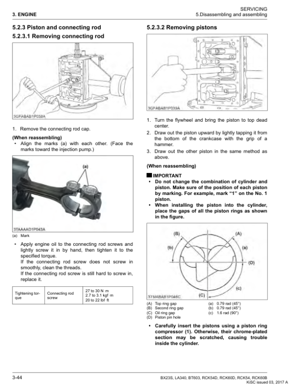
- Piston, Piston Rings and Connecting Rod
- Crankshaft, Camshaft, Rocker Arms and Flywheel
- Engine Timing Gear Mechanism
- Lubrication System — Oil Strainer, Pump and Filter
- Lubrication Relief Valve and Oil Pressure Switch
- Cooling System — Water Pump, Radiator and Radiator Cap
- Fuel System — Filter, Feed Pump and Injection Nozzles
- Engine Troubleshooting, Service Specifications and Tightening Torques
- Engine Compression Pressure and Valve Clearance Checks
- Engine Oil Pressure Testing
- Fuel Injection Timing Inspection
- Engine Removal and Separation from Tractor
- Engine External Component Disassembly
- Cylinder Head, Valves and Timing Gear Disassembly/Assembly
- Piston, Connecting Rod, Flywheel and Crankshaft Disassembly/Assembly
- Cylinder Head Flatness and Valve Guide Inspection
- Valve Seats, Valve Springs and Rocker Arm Servicing
- Timing Gear Backlash and Camshaft Inspection
- Governor Gear and Idler Gear Bushing Servicing
- Piston Pin, Connecting Rod and Piston Ring Inspection
- Crankshaft Alignment and Bearing Clearance Checks
- Cylinder Wear Inspection and Oversize Correction
- Oil Pump Clearance and Relief Valve Servicing
-
04. Transaxle and Hydrostatic Transmission (HST)
- Transaxle Construction and Power Train
- Hydrostatic Transmission Structure and Oil Flow
- HST Control Linkage and Speed-Set Linkage
- Range Gear Shift Mechanism
- Front-Wheel-Drive Transmission Section
- Differential Gear and Differential Lock Mechanisms
- Transaxle Brake System Construction
- Power Take-Off (PTO) Clutch and Relief Valve
- Mid-PTO and Rear-PTO Drive Systems
- Hydraulic Pump Drive Gear Mechanism
- Transaxle Troubleshooting and Service Specifications
- Transaxle Tightening Torques
- HST Neutral and Drive-System Adjustment
- Transaxle Removal and Separation from Tractor
- HST Center Section, Valve Plates and Relief Valve Components
- HST Cylinder Block, Pistons and Swashplate Disassembly
- HST Neutral Arm, Trunnion Arm and Pump Shaft
- Transaxle Shaft, Rear Axle Case and Differential Disassembly
- PTO Clutch Assembly Removal
- HST Center Section and Cylinder Block Inspection
- HST Bearings, Thrust Plates and Pump Shaft Inspection
- PTO Clutch Disc, Pressure Plate and Spring Wear Checks
- PTO Brake Disc and Brake Plate Inspection
- Differential Gear Clearances and Bevel Gear Backlash
- Brake Cam, Actuator and Friction Plate Inspection
-
05. Front Axle and Four-Wheel-Drive Components
- Front Axle Structure and Operating Mechanism
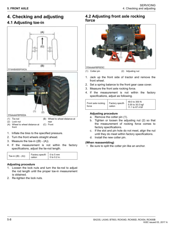
- Front Wheel Alignment — Camber, Kingpin Angle, Caster and Toe-In
- Front Axle Troubleshooting and Service Specifications
- Front Axle Tightening Torques
- Toe-In and Front Axle Rocking Force Adjustment
- Front Axle Assembly Removal and Separation
- Power Steering Cylinder Removal
- Front Bevel Gear and Front Gear Case Disassembly
- Front Axle Shaft and Bevel Pinion Removal
- Differential Gear Disassembly and Assembly
- Differential Side Gear and Pinion Clearances
- Differential and Bevel Gear Backlash Checks
- Bevel Pinion Shaft Turning Torque Inspection
- Center Pin and Support Bushing Clearance Checks
-
06. Power Steering System
- Power Steering System Structure
- Steering Hydraulic Circuit
- Steering Controller — Control Valve and Metering Device
- Steering Relief Valve and Steering Cylinder
- Steering Troubleshooting and Service Specifications
- Steering Tightening Torques
- Relief Valve Operating Pressure Test
- Power Steering Cylinder and Tie-Rod Removal
- Steering Wheel and Controller Removal
- Steering Cylinder Disassembly and Assembly
- Steering Cylinder Bore and Rod Clearance Inspection
-
07. Hydraulic System and Loader Control Circuits
- Hydraulic System Structure and Circuit Diagram
- Hydraulic Pump Construction and Specifications
- Main Control Valve Construction and Operation
- Control Valve Neutral, Lift and Lowering Functions
- Flow Priority Valve Structure and Operation
- Hydraulic Relief Valve Construction and Function
- Hydraulic Lift Cylinder and Block-Type Outlet
- Mower Lift Linkage Mechanism
- Front Loader Control Valve and Hydraulic Piping
- Front Loader Hydraulic Circuit
- Loader Valve Neutral, Raise and Lower Functions
- Loader Float, Rollback and Bucket Dump Functions
- Hydraulic Troubleshooting, Specifications and Tightening Torques
- Hydraulic Relief Valve Setting Pressure Test
- Hydraulic Pump and Power Steering Oil Flow Measurement
- Hydraulic Pump Removal and Disassembly/Assembly
- Hydraulic Cylinder Block Removal
- Hydraulic Lift Cylinder and Control Valve Disassembly
- Lift Arm, Arm Shaft and Lowering-Speed Valve Removal
- Mower Lift Linkage Disassembly
- Front Loader Control Valve Removal and Disassembly
- Hydraulic Pump Gear, Shaft and Bushing Clearance Inspection
- Hydraulic Cylinder Bore and Arm Shaft Bushing Inspection
-
08. Electrical System and Diagnostics
- BX Tractor Electrical Wiring Diagram
- Electrical Connector Identification and Circuit Symbols
- Electrical Connector Handling Precautions
- Engine Starting System, Starter and Glow Plugs
- Starting Safety Switch and Fuel Pump Circuits
- Operator Presence Control (OPC) Timer Circuit
- Charging System and IC Regulator
- Lighting System Electrical Circuit
- Hour Meter, Tachometer and Fuel Gauge
- Coolant Temperature Sensor and Oil Pressure Switch
- Accessory Circuit and DC Power Outlet
- Electrical Troubleshooting and Service Specifications
- Battery Voltage, Terminal and Specific Gravity Checks
- Main Switch Voltage and Continuity Testing
- Starter Motor, Magnetic Switch and Glow Plug Testing
- PTO Safety Switch and HST Neutral Switch Inspection
- Operator Seat Switch and OPC Timer Testing
- Fuel Pump, Engine Stop Solenoid and Timer Relay Checks
- Charging Current and Combination Switch Testing
- Lighting, Hazard Switch and Flasher Unit Tests
- Fuel Level, Coolant Temperature and Oil Pressure Sensor Checks
- Meter Panel and Accessory Outlet Testing
- Starter Motor Disassembly and Assembly
- Alternator and IC Regulator Disassembly/Assembly
- Starter Overrunning Clutch and Brush Inspection
- Alternator Stator, Rotor, Bearings and Rectifier Servicing
-
09. Rotary Mower — Mechanism and Servicing
- Mower Power Transmission System
- Mower Troubleshooting and Service Specifications
- Mower Tightening Torques
- RCK54D-26BX and RCK60D-26BX Mower Setup References
- Mower Frame Link and Tractor Mounting
- Mower Linkage and Cutting Height Adjustment
- Left-to-Right Mower Deck Levelling
- Mower Blade and Drive Belt Inspection
- Mower Ramp and Belt Cover Removal
- Mower Blade and Blade Boss Removal
- Mower Gearbox and Drive Belt Removal
- Mower Gearbox Disassembly and Assembly
- Mower Pulley Holder and Blade Shaft Disassembly
- Gearbox Pinion Shaft Turning Torque Adjustment
- Mower Bevel Gear Backlash Adjustment
-
10. LA340 Front Loader — Mechanism and Servicing
- Front Loader Hydraulic Circuit Diagram
- Boom Cylinder and Bucket Cylinder Construction
- One-Touch Front Loader Attachment System
- One-Lever Quick-Touch Four-Line Hydraulic Coupler
- Automatic Loader Attachment Locking and Detachment
- Mechanical Loader Frame Standing Mechanism
- Optional Third-Function Hydraulic Valve
- Third-Function Activation Switch and Valve Operation
- Front Loader Troubleshooting and Tightening Torques
- Loader Stand Height Adjustment
- Front Hydraulic Valve Main Switch Continuity Testing
- Front Hydraulic Valve Switch Voltage and Relay Checks
- Loader Bucket, Boom and Hydraulic Cylinder Disassembly
- Loader Hydraulic Cylinder Piston and Rod Removal
- Hydraulic Cylinder Piston Seal and O-Ring Replacement
- Loader Side Frame and Front Guard Removal
- Loader Main Frame Removal
- Third-Function Valve and Hydraulic Tube Removal — If Equipped
- Loader Hydraulic Cylinder Piston Rod Bend Inspection
-
11. BT603 Backhoe — Mechanism and Servicing
- Backhoe Hydraulic Circuit Diagram
- Backhoe Main Control Valve Construction
- Control Valve Neutral and Swing Functions
- Backhoe Boom Raising and Lowering Circuits
- Left and Right Stabilizer Hydraulic Functions
- Dipperstick Crowd and Extension Circuits
- Bucket Rollback and Dump Circuits
- Overload Relief and Anti-Cavitation Valve Operation
- Backhoe Hydraulic Cylinder Construction
- Backhoe Troubleshooting, Specifications and Tightening Torques
- Backhoe Removal and Mounting Pin Release
- Bucket Removal and Dipperstick Disassembly
- Boom, Dipperstick and Bucket Cylinder Removal
- Backhoe Swing Frame and Swing Cylinder Removal
- Stabilizer and Stabilizer Cylinder Removal
- Backhoe Control Lever Support and Control Valve Removal
- Backhoe Main Frame Disassembly
- Backhoe Control Valve Disassembly
- Boom, Dipperstick, Bucket, Swing and Stabilizer Cylinder Disassembly
- Hydraulic Cylinder Piston Seal and O-Ring Replacement
- Backhoe Pin and Bushing Clearance Inspection
- Thrust Washer Wear Inspection
- Hydraulic Cylinder Piston Rod Bend Inspection
Loader Quick-Attach Systems, Backhoe Hydraulics and Mower Applicability
The LA340 Front Loader chapter describes one-touch loader mounting, the four-line hydraulic coupler, automatic attachment locking and the mechanical loader stand. It also provides separate testing and removal information for the optional third-function valve. Loader cylinder servicing includes piston seal and O-ring replacement, while the hydraulic references explain the lift, lower, float, rollback and bucket-dump control functions.
The BT603 Backhoe chapter contains its own hydraulic circuit and control-valve information, distinguishing boom, dipperstick, bucket, swing and stabilizer operations. Service procedures address attachment removal, hydraulic cylinder disassembly, valve servicing, pin and bushing clearance, thrust washer wear and piston rod inspection. The mower chapter separately provides setup and servicing references for the identified RCK-series equipment, including RCK54D-26BX and RCK60D-26BX configurations. Select each procedure according to the installed attachment and its model identification.




























Reviews
There are no reviews yet.