Overview
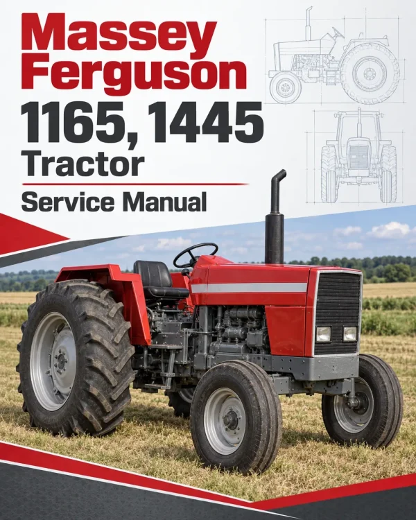
The Massey Ferguson 1165 and 1445 Tractor Workshop Service Repair Manual provides detailed technical information for maintaining, troubleshooting and repairing these Massey Ferguson agricultural tractors. The workshop documentation covers four-cylinder Iseki diesel engines, cooling and fuel systems, clutch assemblies, standard and Power Shuttle transmissions, four-wheel-drive front axles, rear axle components, braking systems, power steering, hydraulic lift equipment and electrical systems. It also provides tractor identification, servicing specifications, maintenance schedules and major component separation procedures.
Technical coverage includes engine cylinder head and crankshaft overhaul, diesel injection pump servicing, clutch adjustment, transmission synchroniser repairs, Power Shuttle hydraulic controls, front differential servicing, rear brake adjustment and hydraulic pump overhaul. Additional chapters address three-point hitch components, PTO clutch mechanisms, draft and position control adjustments, Orbit-Roll steering units, electrical wiring harnesses, instrument panel servicing, engine glow plug systems and mechanical assembly repairs. The documentation includes serial-number-dependent references and specifications for related ST45 and MT295 tractor configurations.
Important Information: The workshop manual identifies certain components and specifications according to tractor model and serial number, including configurations prior to and effective from the “M” serial-number designation. It also distinguishes standard transmission and Power Shuttle arrangements, with separate references for their controls and hydraulic equipment. Verify the tractor model, serial number and installed components before selecting the applicable service instructions.
Table of Contents
Massey Ferguson 1165, 1445 Manual
- 01. Introduction, Specifications and Maintenance
- Workshop Manual Introduction and Indexing
- Special Workshop Tools
- Repair and Replacement Procedures
- Repair Time Schedule
- Workshop Manual Amendments
- General Safety Precautions
- Tractor Identification
- Model and Serial Number Identification
- Special Component Tightening Torques
- Standard Torque Chart
- Tractor Specifications and Fluid Capacities
- Engine Oil and Coolant Capacities
- Fuel Tank Capacity
- Transmission and Differential Housing Capacities
- Four-Wheel-Drive Front Axle Capacity
- Grease Fitting Identification
- Periodic Maintenance Schedule
- Lubrication and Fluid Filling Points
- Major Component Identification – Prior to “M” Serial Number
- Major Component Identification – Effective “M” Serial Number
- General Tractor Specifications
- Wheel and Tyre Specifications
- Tyre Inflation Pressures
- Wheel Bolt Tightening Torques
- Transmission Speed References
- Workshop Sealants and Adhesives
- 02. Sheet Metal and Three-Point Hitch
- Engine Hood Side Panel Removal and Installation
- Front Grille Removal and Installation
- Engine Hood Removal and Installation
- Steering Column Cover Removal and Installation
- Instrument Panel Shroud Removal and Installation
- Roll-Over Protective Structure (ROPS) Frame
- ROPS Frame Removal and Installation
- Tractor Fender Removal and Installation
- Operator Seat Removal and Installation
- Seat Suspension Removal and Installation
- Floor and Fender Assembly
- Floor Mount Removal and Installation
- Engine Muffler Removal and Installation
- Drawbar Removal and Installation
- Drawbar Bracket Removal and Installation
- Category 1 Three-Point Hitch Specifications
- Three-Point Hitch Top Link
- Lift Rod and Lower Link Removal and Installation
- Extendable Lower Link
- Three-Point Hitch Check Chain
- Under-Seat Panel Removal and Installation
- 03. Major Components and Tractor Separation
- General Precautions for Tractor Separation
- Major Component Reinstallation Precautions
- Standardised Component Installation Procedures
- Roller and Ball Bearing Installation
- Oil Seal Installation Precautions
- O-Ring Installation
- Snap Ring Installation
- Spring Roll Pin Installation
- Cotter Pin Installation
- Bolt and Nut Installation Precautions
- Workshop Adhesive Application
- Component Sealant Application
- Major Tractor Component Separation
- Four-Wheel-Drive Front Drive Shaft Removal
- Front Axle and Front Axle Bracket Removal
- Front Axle and Bracket Reinstallation
- Front Axle with Front and Rear Brackets
- Engine Separation from Front Transmission
- Engine Separation from Chassis
- Engine Removal and Reinstallation
- Front Transmission Separation from Spacer Transmission
- Standard and Power Shuttle Transmission Separation References
- Spacer Transmission Separation from Differential
- Rear Axle Housing Removal at Differential
- Hydraulic Cylinder Cover Removal and Installation
- 04. Engine Cooling System and Air Cleaner
- Cooling System General Description
- Cooling System Specifications
- Radiator Removal and Installation
- Radiator Inspection
- Radiator Leak Testing with Compressed Air
- Radiator Cap Pressure Testing
- Radiator Clogging Inspection
- Radiator Exterior Inspection
- Radiator Cap Inspection
- Radiator Reassembly
- Cooling System Function Testing
- Daily Cooling System Inspection
- Engine Antifreeze Requirements
- Antifreeze Filling Precautions
- Radiator Hose Removal and Installation
- Cooling Fan Belt Removal and Installation
- Engine Water Pump Removal and Installation
- Water Pump Overhaul
- Water Pump Impeller and Seal Unit
- Cooling Fan Centre Assembly
- Engine Thermostat Removal and Installation
- Thermostat Operating Test
- Cooling System Troubleshooting
- Engine Air Cleaning System
- Air Cleaning System Specifications
- Engine Air Cleaner Servicing
- 05. Four-Cylinder Iseki Diesel Engine
- Iseki Diesel Engine General Information
- Four-Cylinder Engine Specifications
- Engine Workshop Service Standards
- Engine Servicing Precautions
- Preparation for Engine Service
- Engine Component Tightening Torques
- Engine Troubleshooting
- Engine Inspection and Preparation
- Engine Starting and Operating Precautions
- Periodic Engine Inspection
- Engine Fuel System Air Bleeding
- Engine Long-Term Storage
- Cylinder Head Inspection and Servicing
- Engine Combustion Process
- Cylinder, Piston and Connecting Rod Inspection
- Crankshaft Inspection and Servicing
- Intake and Exhaust Valve Mechanisms
- Engine Oil Draining
- Cooling Fan Belt Removal
- Engine Solenoid, Alternator and Starter Removal
- Intake and Exhaust Manifold Removal
- Cylinder Head Cover Removal
- Fuel Injection Nozzle Removal
- Crankshaft Pulley and Water Pump Removal
- Cylinder Head Removal
- Engine Timing Gear Case Removal
- Fuel Injection Pump Removal
- Flywheel and Rear Plate Removal
- Timing Gears and Front Plate Removal
- Oil Pan and Strainer Removal
- Piston and Connecting Rod Removal
- Crankshaft Removal
- Crankshaft Reinstallation
- Piston and Connecting Rod Reassembly
- Oil Strainer and Oil Pan Installation
- Rear Plate and Flywheel Installation
- Front Plate and Timing Gear Installation
- Fuel Injection Pump Installation
- Timing Gear Case Installation
- Crankshaft Pulley and Water Pump Installation
- Cylinder Head Reinstallation
- Fuel Injection Nozzle Installation
- Intake and Exhaust Manifold Installation
- Fuel Injection Pipe Installation
- Engine Cylinder Head Cover Installation
- Engine Solenoid and Alternator Installation
- Cooling Fan Installation
- Engine Lubrication System
- Engine Oil Pump
- Engine Lubrication Diagram
- Engine Oil Filter
- Engine Oil Pressure Relief Valve
- Engine Cooling and Thermostat Components
- Water Pump Servicing
- Cooling Fan Belt Adjustment
- Diesel Fuel System Diagram
- Fuel Injection Pump Servicing
- Injection Pump Removal and Disassembly
- Injection Pump Inspection and Reassembly
- Fuel Injection Volume Adjustment
- Injection Nozzle and Nozzle Holder
- Engine Fuel Governor
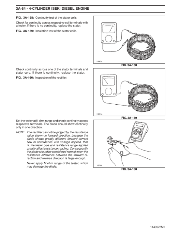
- Engine Alternator Specifications and Construction
- Alternator Troubleshooting
- Alternator Removal and Disassembly
- Alternator Inspection and Reassembly
- Engine Glow Plug Construction and Operation
- Glow Plug Inspection
- Engine Shut-Off Solenoid Specifications
- Engine Speed Pickup
- Starter Motor Construction
- Starter Motor Removal and Disassembly
- Starter Motor Component Inspection
- Starter Motor Reassembly
- Starter Motor Performance Testing
- Starter Motor Installation and Service Standards
- 06. Clutch System
- Clutch General Description
- Clutch System Specifications
- Main Clutch Removal and Installation
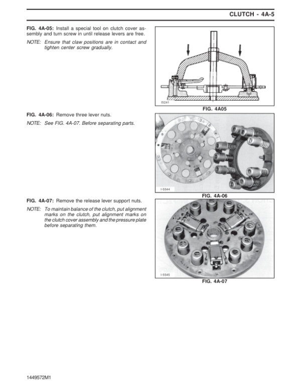
- Main Clutch Overhaul
- Clutch Component Inspection
- Clutch Pressure Plate Inspection
- Clutch Pressure Spring Adjustment
- Clutch Pressure Spring Inspection
- Main Clutch Reassembly
- Clutch Release Bearing Removal and Installation
- Release Bearing Inspection
- Release Bearing Reassembly
- Clutch Cross Shaft and Related Components
- Clutch Cross Shaft Removal and Installation
- Clutch Cross Shaft Disassembly and Inspection
- Clutch Cross Shaft Reassembly
- Clutch Pedal Free-Play Adjustment
- Clutch Rod Linkage Removal and Installation
- Clutch System Troubleshooting
- 07. Transmission – Standard and Power Shuttle
- Transmission General Description
- Wheel Drive System
- Power Take-Off Drive System
- Transmission Power Train Diagram
- Transmission Specifications
- Standard Transmission Speed Shift Patterns
- Transmission Gear Train Diagrams
- Transmission Input Gear Construction
- PTO Clutch and Forward/Reverse Shuttle Clutch
- Transmission Clutch Pack Oil Supply
- Hydraulic Pipe Joint Tightening Torques
- Transmission Reducing Valve and Piping
- Hydraulic Reducing Valve Operation
- PTO Solenoid Operation
- PTO Timer Control Unit
- PTO Timer Relay Location
- Power Shuttle Control Lever
- Power Shuttle Lever and Switch Installation
- Power Shuttle Control Switches
- Power Shuttle Valve Assembly
- Forward and Reverse Shuttle Valve
- Power Shuttle Clutch Disassembly
- Power Shuttle Clutch Reassembly
- Transmission PTO Clutch Overhaul
- PTO Clutch Disassembly and Inspection
- PTO Clutch Disc and Driven Plate Inspection
- PTO Brake Disc Inspection
- Mechanical Shuttle Reassembly
- Transmission Input Section Removal
- Input Housing and Gear Removal
- Transmission Input Shaft Installation
- Forward and Reverse Gear Assemblies
- Forward and Reverse Synchroniser
- Reverse Shaft Disassembly and Inspection
- Reverse Shaft Reassembly
- Main Transmission Change Gears
- Main Transmission Counter Gear Disassembly
- Main Transmission Gear Overhaul
- Main Transmission Gear Inspection and Reassembly
- Main Transmission Shift Forks
- Range Shift Gear Removal and Overhaul
- Rear Differential Transmission Components
- Ring Gear and Drive Pinion Removal
- Ring Gear and Pinion Overhaul
- Ring Gear Tooth Contact Inspection
- PTO Shaft and Related Components
- PTO Shaft Removal and Disassembly
- PTO Shaft Reassembly
- PTO Shift Mechanism
- Standard Shuttle Forward/Reverse Linkage
- Standard Shuttle Control Cable
- Main Transmission Shift Linkage
- Range Shift Linkage
- Four-Wheel-Drive Shift Mechanism
- Front Transmission Case Removal
- Centre Transmission Case Removal
- Rear Differential Housing Removal
- Wheel Drive System Troubleshooting
- PTO Drive System Troubleshooting
- 08. Four-Wheel-Drive Front Axle
- Four-Wheel-Drive Front Axle General Description
- 4WD Front Axle Specifications
- Front Wheel Drive Shaft Removal and Installation
- Front Axle Pivot Bracket Bushings
- Pivot Bushing Removal and Installation
- Pivot Bracket Reassembly
- Four-Wheel-Drive Front Track Adjustment
- Front Wheel Alignment
- Front Differential Assembly
- Front Differential Removal and Installation
- Front Differential Overhaul
- Front Differential Inspection
- Front Differential Reassembly
- Front Wheel Final Drive Assembly
- Front Wheel Shaft Seal and Cover
- Front Axle Centre Section Removal and Installation
- Front Axle Bracket Oil Seal Replacement
- Final Drive Housing Overhaul
- Final Drive Housing Disassembly
- Final Drive Component Inspection
- Final Drive Housing Reassembly
- Four-Wheel-Drive Front Axle Troubleshooting
- 09. Rear Axle, Differential and Brakes
- Rear Axle General Description
- Rear Axle and Brake Specifications
- Rear Final Drive Gear Removal and Installation
- Rear Axle Shaft Removal and Installation
- Rear Axle Oil Seal and Bearing Replacement
- Brake Disc Removal and Installation
- Rear Brake Overhaul
- Brake Friction Plate Inspection
- Brake Actuator Inspection
- Brake Separator Plate Inspection
- Rear Brake Reassembly
- Differential Lock Clutch Removal and Installation
- Rear Axle Housing Replacement
- Brake Boot Removal and Installation
- Rear Brake Adjustment
- Brake Rod Removal and Installation
- Brake Pedal Removal and Installation
- Parking Brake Removal and Installation
- MF 1165 Rear Axle Assembly
- Rear Axle and Brake Troubleshooting
- 10. Power Steering System
- Power Steering System Construction
- Power Steering Component Identification
- Integral Orbit-Roll Steering Unit
- Power Steering Unit Disassembly
- Steering Rotor-Side Disassembly
- Steering Control-Side Disassembly
- Steering Unit Component Inspection
- Power Steering Unit Reassembly
- Steering Control-Side Reassembly
- Steering Gerotor-Side Reassembly
- Power Steering System Troubleshooting
- 11. Hydraulic System and Three-Point Linkage
- Hydraulic System General Description
- Hydraulic System Specifications
- Three-Point Linkage Hydraulic Pump
- Transmission and Hydraulic Oil Replacement
- Hydraulic Cartridge Filter Replacement
- Hydraulic Suction Filter Replacement
- Hydraulic Pump Removal and Installation
- Hydraulic Pump Overhaul
- Hydraulic Pump Disassembly
- Hydraulic Pump Inspection and Repair
- Hydraulic Pump Gear Inspection
- Hydraulic Pump O-Rings and Oil Seals
- Hydraulic Pump Reassembly
- Hydraulic Pump Inspection After Reassembly
- Hydraulic Linkage System Overhaul
- Hydraulic Linkage Reassembly
- Hydraulic Draft Spring and Housing
- Hydraulic Lift Shaft and Crank
- Hydraulic Cylinder and Piston Removal
- Hydraulic Linkage Adjustment
- Hydraulic Position Control Adjustment
- Hydraulic Draft Control Adjustment
- Position and Draft Control Operating Principles
- Hydraulic Main Control Valve
- Hydraulic Main Spool
- Hydraulic Unloading Valve and Compensator
- Hydraulic Holding Check Valve
- Hydraulic Pilot Spool
- Main Control Valve Neutral Position
- Hydraulic Lift Raising Position
- Hydraulic Lift Lowering Position
- Hydraulic Unloading Process
- Main Control Valve Removal and Installation
- Main Control Valve Disassembly and Reassembly
- PTO Hydraulic Control Valve – Standard Transmission
- PTO Solenoid Changeover Valve
- Hydraulic Pressure-Reducing Valve
- PTO Valve Flow Divider
- PTO Flow Divider Removal and Overhaul
- Transmission Pressure Control Valve – Standard Transmission
- PTO Pressure Control Valve – Standard Transmission
- Main Hydraulic Relief Valve
- Main Relief Valve Pressure Testing
- Hydraulic Cylinder Protection Relief Valve
- Hydraulic Flow Control and Slow-Return Check Valve
- Slow-Lowering Check Valve Replacement
- Hydraulic Cylinder Cover Replacement
- Hydraulic Piston Lift Rod
- Optional Remote Hydraulic Control System
- Remote Hydraulic Control Valve Specifications
- Single-Acting and Double-Acting Hydraulic Oil Flow
- Hydraulic Control Ports and Functions
- Remote Hydraulic Control Valve Removal and Overhaul
- Hydraulic System Troubleshooting
- 12. Electrical System and Instrumentation
- Electrical System General Information
- Electrical Formulas and Specifications
- Battery Removal and Installation
- Battery Inspection
- Instrument Panel Removal and Installation
- Engine Tachometer Removal and Inspection
- Fuel Gauge and Sensor Testing
- Fuel Gauge Removal and Installation
- Lower Fuel Tank Sensor – Prior to “M” Serial Number
- Upper Fuel Tank Sensor Removal and Installation
- Coolant Temperature Gauge Removal and Installation
- Engine Coolant Temperature Sensor
- Starter Switch Removal and Inspection
- Lighting, Turn Signal and Horn Switch
- Electrical Safety Switches
- PTO Safety Relay
- PTO Safety Relay Removal and Installation
- Power Take-Off Electrical Switch
- Horn Removal and Installation
- Engine Shut-Off Solenoid Testing
- Engine Shut-Off Solenoid Removal and Installation
- Electrical Wiring Harness Removal and Installation
- Wiring Harness – Effective “M” Serial Number
- Front Headlight Bulb Replacement
- Signal Light and Tail Light Bulb Replacement
- Instrument Panel Light Bulb Replacement
- Engine Glow Indicator System
- Glow Indicator Circuit Testing
- Glow Plug Indicator Replacement
- Engine Glow Plug Replacement
- Power Shuttle Electrical Wiring Harness
- Power Shuttle Component Layout
- Lighting System Troubleshooting
- Instrumentation Troubleshooting
- Engine Glow System Troubleshooting
Serial Number and Transmission Configuration References
The Massey Ferguson 1165 and 1445 workshop documentation identifies several components by serial-number applicability. The introduction includes major component references for tractors prior to and effective from the “M” serial-number designation. The electrical chapter also distinguishes certain fuel tank sensors and wiring harness arrangements according to serial-number range.
The transmission documentation provides separate references for standard mechanical shuttle and Power Shuttle equipment, including shuttle controls, clutch assemblies, hydraulic reducing valves, solenoid operation and PTO control components. Related hydraulic chapters identify PTO pressure control valves and other components specifically applicable to standard transmission configurations.
Before servicing these systems, confirm the tractor’s model and serial number and identify the fitted transmission. This helps select the relevant electrical component layout, drivetrain service instructions and hydraulic control references.



























Reviews
There are no reviews yet.