Overview
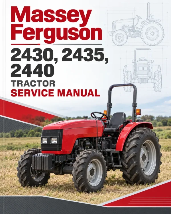
The Massey Ferguson 2430, 2435 and 2440 Tractor Workshop Service Repair Manual provides technical information for maintaining, troubleshooting and repairing these Massey Ferguson agricultural tractors. The documentation covers engine systems, clutch and Hi-Lo assemblies, Speedfive and Powerfive mechanical gearboxes, rear axle and final drives, front axle components, power take-off equipment, hydraulic lift systems, hydrostatic steering, brakes, electrical equipment and cab air conditioning.
Technical coverage includes engine compression testing, fuel injection adjustments, clutch overhaul, gearbox synchronisation and shaft adjustments, differential bearing preload settings, hydraulic control valve servicing and Orbitrol steering unit repairs. Additional references address mechanical power lift position and draft control, trailer braking hydraulics, electrical wiring diagrams, charging and starting systems, instrumentation, electronic lift circuits and air-conditioning troubleshooting.
Notice: The workshop documentation distinguishes Speedfive and Powerfive gearboxes, standard and GT/GS final drive references, multiple hydraulic valve arrangements, and electrical equipment configurations. Consult the sections corresponding to the tractor’s installed components.
Table of Contents
Massey Ferguson 2430, 2435, 2440 Manual
-
01. General Information and Workshop Safety
- Workshop Manual Introduction and Purpose
- Safety Notes and Personal Risk
- Accident Prevention and General Safety Rules
- Engine Starting Safety
- Engine Servicing Precautions
- Electrical System Safety
- Hydraulic Circuit Safety
- Wheel and Tyre Safety
- Unhitching and Re-Hitching Precautions
- General Workshop Instructions
- Battery Servicing Instructions
- Adjuster Shims
- Rotating Shaft Oil Seals
- O-Ring Seals
- Bearings and Spring Pins
- Spare Parts Information
- Specific Workshop Equipment
- Workshop Symbols and Their Meanings
- Safety and Danger Decal Locations – WEO Markets
- Sealing and Fixing Compounds
- Lubricants and Fuels
- International Measurement Units
- Imperial Measurement Conversions
- Standard Metric Screw Tightening Torques
- Standard Metric Nut Tightening Torques
-
02. Engine Service and Adjustments
- Engine General Features
- Engine Component Views
- Fuel Injection Pump
- Diesel Fuel Injectors
- Engine Turbocharger
- Engine Lubrication Circuit
- Engine Fuel Supply Circuit
- Engine Cooling Circuit
- Engine Intake and Exhaust Circuit
- Engine Troubleshooting
- Engine Cylinder Compression Testing
- Compression Ratio Reference
- Cylinder Compression Measurement Procedure
- Engine Valve Clearance Adjustment
- Engine Drive Belt Tension Inspection
- Fuel Injection Pressure Testing
- Injector Spray Inspection
- Fuel Injection Pump Adjustment and Tuning
-
03. Clutch and Hi-Lo System
- 12-Inch Clutch Technical Specifications
- Hi-Lo System Technical Specifications
- Clutch Operating Principles
- Hi-Lo System Operating Principles
- Clutch Controls
- Clutch Assembly Sectional Views
- Clutch Housing Sealant Application Diagram
- Clutch Assembly Troubleshooting
- Clutch Removal from Tractor
- Clutch Reinstallation
- Clutch Housing Overhaul
- Clutch Housing Disassembly
- Clutch Housing Reassembly
- Clutch Housing with Hi-Lo System Overhaul
- Hi-Lo Clutch Housing Disassembly
- Hi-Lo Clutch Housing Reassembly
- Reverse Shuttle End Float Adjustment
-
04. Speedfive and Powerfive Mechanical Gearboxes
- Speedfive Gearbox Technical Specifications
- Speedfive Final Drive Specifications
- Speedfive Reverse Shuttle Specifications
- Speedfive Gearbox Operating Principles
- Speedfive Gearbox and Reverse Shuttle
- Speedfive Super Final Drive
- Powerfive Gearbox Technical Specifications
- Powerfive Reverse Shuttle Specifications
- Powerfive Super Final Drive Specifications
- Powerfive Gearbox Operating Principles
- Powerfive Gearbox and Reverse Shuttle
- Powerfive Super Final Drive
- Gearbox Controls
- Gearbox Sectional and Perspective Views
- Gearbox Housing Sealant Application Diagram
- Gearbox and Range Reduction Troubleshooting
- Reverse Shuttle Troubleshooting
- Super Final Drive Troubleshooting
- Gearbox Removal from Tractor
- Gearbox Reinstallation
- Gearbox Housing Overhaul
- Gearbox Housing Disassembly
- Gearbox Housing Reassembly
- Four-Gear Pack End Float Adjustment
- Fourth-Gear Synchronisation End Float Adjustment
- Gear Lever Support Housing Disassembly
-
05. Rear Axle, Differential and Front Axle
- Standard Rear Bevel Gear and Differential Specifications
- Standard Rear Side Final Drive Specifications
- GT Bevel Gear and Differential Specifications
- GT Side Final Drive Specifications
- Rear Axle Operating Principles
- Bevel Gear and Rear Differential Troubleshooting
- Side Final Drive Troubleshooting
- Rear Axle Controls
- Rear Axle Component Views
- Differential Housing Sealant Application
- Standard Final Drive Housing Sealant Application
- GT Final Drive Housing Sealant Application
- Rear Differential Housing Removal and Refitting
- Rear Differential Housing Disassembly
- Rear Differential Housing Reassembly
- Rear Differential Pinion Position Adjustment
- Pinion Tapered Bearing Preload Adjustment
- Differential Support Bearing Preload Adjustment
- Pinion and Crownwheel Tooth Clearance Adjustment
- Standard Side Final Drive Overhaul
- Standard Side Final Drive Disassembly and Reassembly
- Rear Axle Shaft Tapered Bearing Preload Adjustment
- Wheel Hub Tapered Bearing Preload Adjustment
- GS Side Final Drive Disassembly and Reassembly
- Front Axle Technical Specifications
- Front Axle 710/515
- Front Axle 716/513
- Front Axle Operating Principles and Controls
- Front Axle Sectional Views
- Front Differential Disassembly and Reassembly
- Front Differential Pinion Position Adjustment
- Front Differential Pinion Bearing Preload Adjustment
- Front Pinion and Crownwheel Tooth Clearance Adjustment
- Front Axle Final Drive Disassembly and Reassembly
-
06. Power Take-Off (PTO) System
- Rear Power Take-Off Technical Specifications
- Power Take-Off Operating Principles
- PTO Controls
- Power Take-Off Sectional Views
- PTO Cover Sealant Application Diagram
- Power Take-Off Disassembly
- Power Take-Off Reassembly
-
07. Hydraulic Systems and Rear Power Lift
- Hydraulic System Technical Specifications
- Hydraulic Circuit General Description
- Hydraulic Circuit Diagram
- Low-Flow Hydraulic Circuit
- High-Delivery Hydraulic Circuit
- Hydraulic Steering Circuit
- Hydraulic Pump Construction and Operation
- Hydraulic Unit with Three Solenoid Valves
- Hydraulic Unit with Four Solenoid Valves
- Four-Solenoid Hydraulic Unit for Fast Run
- Hydraulic Unit with Five Solenoid Valves
- Front and Rear Differential Lock Hydraulic Supply
- PTO and PTO Brake Hydraulic Supply
- Hi-Lo Hydraulic Supply Circuit
- Spring-On Hydraulic Supply Circuit
- Hydraulic Trailer Brake Control Valve
- Italian-Version Trailer Brake Valve
- Italian Trailer Brake Valve Operating Phases
- Italian Trailer Brake Valve Release Pressure Inspection and Adjustment
- Export-Version Trailer Brake Valve
- Export Trailer Brake Valve Operating Phases
- Export Trailer Brake Valve Release Pressure Inspection and Adjustment
- Supplementary Hydraulic Distributor
- Hydraulic-Mechanical Rear Power Lift
- Hydraulic Lift Operating Principles
- Hydraulic Lift Component Views
- Rear Power Lift Troubleshooting
- Hydraulic Lift Sealant Application Diagram
- Hydraulic Lift Position Control
- Hydraulic Lift Draft Control
- Mixed Position and Draft Control
- Hydraulic Lift Floating Mode
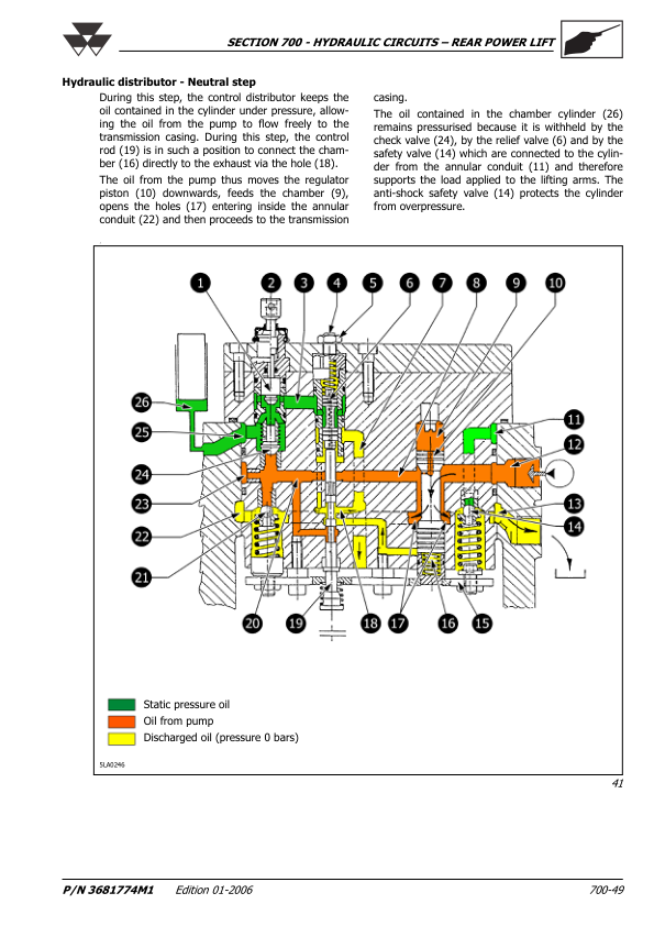
- Hydraulic Distributor Neutral Position
- Hydraulic Distributor Delivery Position
- Hydraulic Distributor Discharge Position
- Hydraulic-Mechanical Power Lift Disassembly
- Hydraulic-Mechanical Power Lift Adjustment
- Hydraulic-Mechanical Power Lift Reassembly
- Hydraulic Distributor Overhaul
- Hydraulic Distributor Disassembly and Reassembly
- Hydraulic System Inspection and Adjustment
- Hydraulic Anti-Shock Valve Inspection and Adjustment
- Hydraulic Discharge Valve Leakage Inspection
- Hydraulic Check Valve Leakage Inspection
- Maximum Pressure Valve Inspection and Calibration
- Hydraulic Delivery Pipe Leakage Inspection
- On-Tractor Hydraulic Lift Adjustments
- Hydraulic Lift Sensitivity Adjustment
- Hydraulic Position Control Adjustment
- Hydraulic Draft Control Adjustment
-
08. Hydrostatic Steering System
- Hydrostatic Steering Technical Specifications
- Hydraulic Steering Circuit Description
- Steering System Sectional and Perspective Views
- Hydrostatic Steering Neutral Position
- Hydrostatic Steering Operating Position
- Manual Steering with Engine Stopped
- Orbitrol Steering Unit Overhaul
- Orbitrol Steering Unit Disassembly
- Orbitrol Steering Unit Reassembly
-
09. Brake System and Adjustments
- Brake System Technical Specifications
- Brake System Operating Principles
- Brake Controls
- Brake System Sectional Views
- Brake Adjustment Procedures
- Rear Brake Adjustment
- Front Brake Adjustment
- Parking Brake Adjustment
-
10. Electrical Systems, Instruments and Wiring Diagrams
- Instrument Panel and Warning Lights
- Instrument Warning Light Identification
- Indicator and External Electrical Connections
- Engine RPM Meter and Hour Counter
- Fuel Level Gauge
- Engine Coolant Temperature Indicator
- Transmitters, Sensors and Solenoid Valves
- Instrument Replacement
- Analogue and Digital Instrument Control Panel
- Hazard Warning Light Switch
- Rotating Beacon Switch
- Ignition Switch
- Steering Column Light Stalk
- Turn Signal Control
- Headlight Flashing Function
- Side and Rear Lighting Controls
- Main and Dipped Beam Controls
- Horn Control
- Working Light Switch – Tractors Without Cab
- Right-Side Controls – Without Electronic Power Lift
- Right-Side Controls – With Electronic Power Lift
- Differential Lock Control Button
- Four-Wheel-Drive and Speed Selection Controls
- Power Take-Off Control Switch
- Electronic Power Lift Control Panel
- External Hydraulic Lift Controls
- Right Cab Pillar Controls
- Cab Air Conditioning and Fan Controls
- Front and Rear Working Light Controls
- Windscreen Washer Switch
- Electrical Cab Components
- ISO Rear Light Configuration
- NAO Rear Light Configuration
- Reverse Light – Japanese Version
- Headlight Bulb Replacement
- Front Position Light and Turn Signal Bulb Replacement
- Rear Light, Brake Light and Indicator Bulb Replacement
- Cab Working Light Bulb Replacement
- Working Light Bulb Replacement – Tractors Without Cab
- Rotating Beacon Bulb Replacement
- Electrical Bulb Specifications
- Starting and Ignition System Specifications
- Ignition System Operating Principles
- Ignition System Testing on Tractor
- Starter Motor Circuit Current Draw Test
- Starting Circuit Voltage Drop Testing
- Positive Battery Cable Inspection
- Starter Motor Ground Connection Inspection
- Battery Ground Cable Inspection
- Starter Motor Removal and Reinstallation
- Charging System Technical Specifications
- Alternator Construction and Operating Principles
- Charging System Testing and Troubleshooting
- Alternator Preliminary Inspection
- Alternator Connection Testing
- Charging Current and Regulated Voltage Testing
- Alternator Component Testing
- Alternator Removal and Reinstallation
- Battery Technical Specifications
- Battery Operation and Servicing
- Battery Removal and Reinstallation
- Battery Electrolyte Relative Density
- Dry-Charged Battery Maintenance
- Battery Charging
- Battery Testing
- Common Battery Faults
- Electrical Circuit Component Identification
- Fuse and Relay Locations
- Main Electrical Fuse Box
- MAXI Fuses
- Main Fuse Box Relays
- Rear Cab Pillar Fuse Box
- Rear Cab Pillar Relays
- Turn Indicator and Hazard Light Circuit – North American ECU
- Seven-Pin Electrical Power Socket
- Electrical Wire Colour Codes
- Wiring Diagram and Connector Identification
- Wiring Diagram A – Rear PTO, 4WD, Speed Selection and Ignition Relay
- Wiring Diagram B – Headlights, Hazard Lights, Differential Lock, Fuel Supply and Starter
- Wiring Diagram C – Instruments, Sensors, Radio, Rotating Beacon, Cab Light and Air Seat
- Wiring Diagram D – Working Lights, Reverse Light and Speed Shift
- Wiring Diagram E – Climate Control, Windscreen Wipers, Fan and Auxiliary Electrical Equipment
- Electronically Controlled Hydraulic Power Lift Components
- Electronic Power Lift Control Unit
- Electronic Power Lift ECU Connections
- Electronic Lift Control Panel Connections
- Wiring Diagram F – Electronic Hydraulic Power Lift
-
11. Cab and Air Conditioning System
- Operator Cab Technical Specifications
- Cab Exterior Components
- Cab Interior Components
- Cab Instruments and Controls
- Air Conditioning System
- Air Conditioning Operating Instructions
- Air Conditioning Starting and Temperature Settings
- Air Conditioning System Shutdown
- Air Conditioning Operating Principles
- Air Conditioning Main Components
- Air Conditioning Compressor
- Air Conditioning Condenser
- Receiver-Drier Filter
- Thermostatic Expansion Valve
- Air Conditioning Evaporator
- Thermostatic Switch and Frost Sensor
- Air Conditioning Temperature Adjustment
- Cab Air Conditioning Maintenance
- Air Conditioning Repair Precautions
- Cab Air Conditioning Troubleshooting
Speedfive, Powerfive and Hydraulic Lift Configuration References
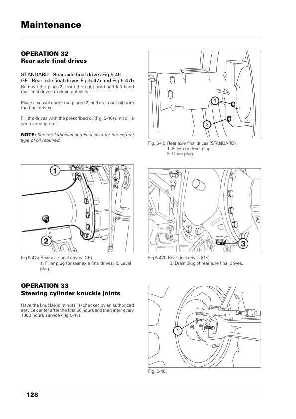
The transmission documentation provides separate technical specifications and operating descriptions for Speedfive and Powerfive mechanical gearboxes. The related rear axle chapter distinguishes standard and GT side final drive specifications, while the overhaul index also identifies a GS side final drive. These designations should be checked against the components fitted to the tractor rather than treated as interchangeable.
The hydraulic chapter includes three-, four- and five-solenoid valve unit arrangements, together with different hydraulic supply circuits for Hi-Lo, differential locking, PTO operation and trailer brakes. The electrical documentation also separates tractors equipped with electronic hydraulic lift controls from those without them, and includes regional lighting configurations. Select the appropriate system reference before following the corresponding adjustment or troubleshooting information.



























Reviews
There are no reviews yet.