Overview
The Massey Ferguson 2705E, 2706E Tractor Workshop Service Manual provides technical information for maintaining, diagnosing and repairing these tractors. It covers machine specifications, component identification, disassembly and installation procedures, service adjustments and troubleshooting references for mechanical, hydraulic and electrical systems.
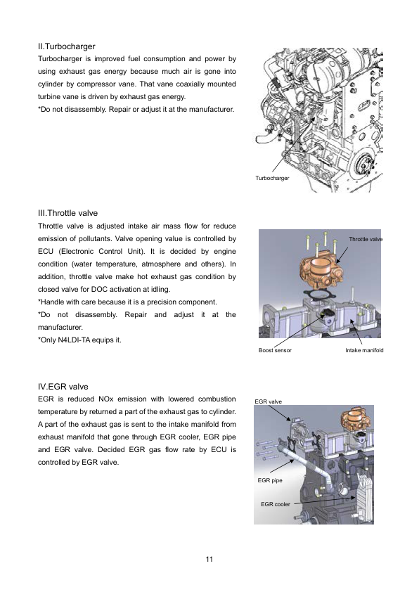
Coverage includes the engine, fuel and exhaust system, clutch and drivetrain assemblies, mechanical and hydrostatic transmissions, front and rear axles, braking, steering and hydraulic equipment. Additional chapters address platform components, power take-off servicing, electronic diagnostics, wiring diagrams, lubrication requirements and hydraulic system troubleshooting.
Safety: The General chapter includes safety messages, operating precautions and maintenance instructions covering power take-off equipment, high-pressure leaks, engine servicing and other workshop activities. Review the applicable safety information before undertaking inspection, maintenance or repair work.
Table of Contents
Massey Ferguson 2705E, 2706E Manual
-
1. General
- 1.1 Introduction
- 1.2 Specifications
- 1.3 General Dimensions
- 1.4 Lubrication / Fill Points
- 1.5 General Precautions for Disassembly and Installation
- 1.6 Tightening Torque Chart
- 1.7 Conversion Table
- 1.8 Safety Introduction
- 1.9 Operation
- 1.10 Maintenance
-
2. Engine, Fuel and Exhaust System
- 2.1 Electronic Diagnostic Tool
- 2.2 Component Access
- 2.3 Removing the Engine
- 2.4 Installing the Engine
- 2.5 Radiator
- 2.6 Air Cleaner System
- 2.7 Fuel Tank
- 2.8 Engine Service Manual
- 2.9 Diagnostic Troubleshooting Codes and Procedures
-
3. Drive Train System
- 3.1 Transmission
- 3.2 Clutch System
- 3.3 Release Bearing
- 3.4 Clutch Assembly
- 3.5 Troubleshooting – Clutch
- 3.6 Clutch Pack and Gear
- 3.7 Input Gears
- 3.8 Power Take-Off
- 3.9 Four-Wheel Drive Gears
- 3.10 Hydrostatic Transmission
-
4. Platform
- 4.1 Platform
- 4.2 Console
- 4.3 Rollover Protective Structure
- 4.4 Steering Wheel
-
5. Axles
- 5.1 Rear Axle
- 5.2 Differential Lock
- 5.3 Ring Gear and Pinion Gear Tooth Pattern
- 5.4 Front Axle
-
6. Brake System
-
7. Electrical System
- 7.1 Wiring Diagrams
- 7.2 Wiring Harness
- 7.3 Fuses, Relays and Diodes
- 7.4 Instruments and Controls
- 7.5 Switches
- 7.6 Sensors
- 7.7 Electronic Diagnostic Tool
-
8. Hydraulic System
- 8.1 Hydraulic System Overview
- 8.3 Power Shuttle Components
- 8.4 General Service Procedures
- 8.5 Suction Filter
- 8.6 Gear Pump
- 8.7 Valves
- 8.8 Hydraulic Control Linkage
- 8.9 Three-Point Lift Linkage and Drawbar
- 8.10 Hydraulic System Troubleshooting
-
9. Steering System
- Index
Mechanical and Hydrostatic Transmission Service Information
The drivetrain documentation covers clutch components, transmission housings, input gears, power take-off assemblies and four-wheel-drive mechanisms. A dedicated hydrostatic transmission section provides component layouts, removal and installation procedures, disassembly and assembly information, inspection procedures and pedal adjustments. Consult the material relevant to the transmission configuration fitted to the tractor.
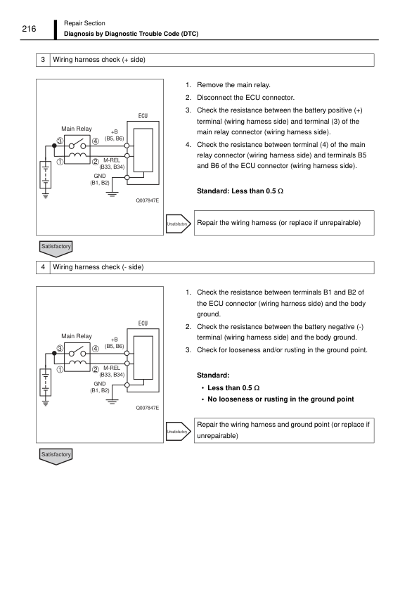
For hydraulic and electrical troubleshooting, the manual provides circuit diagrams, component references and diagnostic procedures. The hydraulic chapters include information on pumps, control valves, filters, three-point linkage controls and system testing, while the electrical chapters cover wiring harnesses, switches, sensors and electronic diagnostic tools. The General section supplies specifications, lubrication points and tightening torque references to support workshop servicing.























Reviews
There are no reviews yet.