Overview
The Massey Ferguson 415, 425, 435 and 440 Tractor Workshop Service Repair Manual provides technical information for maintaining, troubleshooting and repairing these Massey Ferguson MF 400 Series agricultural tractors. The workshop documentation covers Perkins A3.152, A4.236, P4000 and 1000 Series engines, clutch assemblies, mechanical transmissions, rear axle and differential components, Ferguson hydraulic lifting systems, power take-off equipment, electrical systems and auxiliary hydraulics. Separate front axle references address two-wheel-drive configurations, Carraro four-wheel-drive axles and ZF/APL four-wheel-drive assemblies.
Technical coverage includes engine valve clearance adjustment, fuel injection timing, cylinder compression testing, clutch overhaul, transmission shaft and gear repairs, final drive adjustment, differential servicing, hydraulic pump maintenance and independent PTO clutch repairs. Additional sections provide Carraro 20.14, 20.18 and 20.21 axle servicing, ZF/APL 335, 345 and 350 axle overhaul, 8×2 and 12×4 gearbox procedures, brake adjustment, Ferguson draft and position control servicing, electrical component testing, hydrostatic steering repairs and auxiliary hydraulic pressure checks.
Important Information: The workshop manual covers different engine, front axle, clutch and transmission arrangements within the MF 400 Series. It also contains some shared technical references for other MF 400 Series models. Confirm the tractor model and installed components before selecting the appropriate service information. The 8×2 synchromesh gearbox section is identified as reserved in the supplied chapter list and is not presented as a detailed repair section.
Table of Contents
Massey Ferguson 415, 425, 435, 440 Manual
-
01. Introduction, Workshop Safety and Specifications
- Workshop Manual Introduction and Presentation
- Using the Workshop Service Manual
- Recording Manual Changes and Updates
- General Workshop Safety Instructions
- Correct Workshop Repair Techniques
- Basic Measurement Procedures
- Workshop Measuring Instruments
- Measurement Examples and General Concepts
- Recommended Bolt Tightening Torque Tables
- Technical Measurement Units
- Measurement Conversion Tables
- Imperial and SI Unit Equivalents
- Technical Unit Prefixes
- Loctite Products for Workshop Repairs
- AGCO Environmental Policy
- Battery Recycling Requirements
-
02. Splitting the Tractor and Major Component Separation
- Tractor Splitting Introduction
- Separating the Engine from the Front Axle
- Reassembling the Engine and Front Axle
- Separating the Engine from the Gearbox
- Engine and Gearbox Reassembly
- Separating the Gearbox from the Rear Axle
- Gearbox and Rear Axle Reassembly
- ROPS Frame Removal
- Operator Canopy Removal
- Tractor Fender Assembly Removal
- Front Hood and Sheet Metal Removal
-
03. Two-Wheel-Drive Front Axle (2WD)
- Two-Wheel-Drive Front Axle Introduction
- Front Wheel Alignment
- Front Wheel Camber
- Steering Sleeve Inclination
- Front Wheel Caster
- Front Wheel Toe-In Adjustment
- Front Wheel Hub Assemblies
- Front Wheel Hub Disassembly
- Front Wheel Hub Component Inspection
- Front Wheel Hub Reassembly
- Wheel Hub Bearing Preload Adjustment
- Front Axle Outer Arm and Spindle Shaft
- Spindle Shaft Clearance Adjustment
- Spindle Shaft Bushing Replacement
- Front Axle Central Beam
- Central Beam Radial and Axial Clearance Inspection
- Steering System Bushing Replacement – Except MF 415
- MF 415 Front Axle Reference
-
04. Carraro Four-Wheel-Drive Front Axles – 20.14, 20.18 and 20.21
- Carraro 4WD Front Axle General Information
- Carraro Front Axle Technical Specifications
- Front Axle Final Drive
- Final Drive Component Identification
- Final Drive Disassembly
- Final Drive Reassembly and Adjustment
- Front Final Drive Pivot Assembly
- Final Drive Pivot Disassembly
- Final Drive Pivot Reassembly
- Front Half-Shaft Spider Assemblies
- Half-Shaft Spider Disassembly
- Half-Shaft Spider Reassembly
- Front Axle Trumpet Bushings and Retainers
- Pivot Bushing and Retainer Removal
- Axle Bushing Component Inspection
- Bushing and Retainer Reassembly
- Front Differential and Drive Pinion Assembly
- Differential Component Identification
- Carraro Front Axle Removal
- Front Differential Removal and Disassembly
- Front Drive Pinion Disassembly
- Differential and Pinion Inspection
- Drive Pinion Reassembly and Adjustment
- Front Differential Reassembly
- Final Differential and Pinion Adjustments
- Front Drive Box and Bearing Housing
- Drive Box Component Identification
- Drive Box Disassembly
- Drive Box Component Inspection
- Drive Box Reassembly and Adjustment
- Front Bearing Housing and Step-Up Gearbox Bearing Removal
- Hydraulic Steering Cylinder
- Steering Cylinder Disassembly
- Steering Cylinder Component Inspection
- Steering Cylinder Reassembly
- Carraro Front Axle Tightening Torques
-
05. ZF/APL Four-Wheel-Drive Front Axles – APL 335, 345 and 350
- ZF Four-Wheel-Drive Front Axle Introduction
- ZF/APL Front Axle Technical Specifications
- Front Axle Final Drives
- Final Drive Component Identification
- Final Drive Disassembly
- Front Half-Shaft Spider Assemblies
- Final Drive Component Inspection
- Final Drive Reassembly and Adjustment
- Front Differential, Pinion and Axle Trumpets
- Differential Component Identification
- ZF Front Axle Removal
- Front Differential Removal and Disassembly
- Differential Component Inspection
- Front Differential Reassembly and Adjustment
- Drive Pinion Disassembly and Inspection
- Differential Bearing Preload Adjustment
- Drive Pinion Positioning
- Pinion Bearing Preload Adjustment
- Crownwheel and Pinion Backlash Adjustment
- Ring Gear and Pinion Tooth Contact Inspection
- Secondary Drive Box, Brackets and Bearings
- Drive Box Bracket and Bearing Disassembly
- Drive Box Bearing Reassembly and Adjustment
- Secondary Drive Box Disassembly
- Secondary Drive Box Reassembly
- Mechanical Side Drive Box
- Mechanical Drive Box Operating Principles
- Mechanical Side Drive Box Disassembly
- Mechanical Side Drive Box Reassembly
- Spacer and Central Four-Wheel-Drive Box
- Central Drive Box Component Identification
- Central Drive Box Servicing
- Transfer Gearbox Component Identification
- Transfer Gearbox Servicing
- Front Hydraulic Steering Cylinder
- Steering Cylinder Removal and Disassembly
- Steering Cylinder Component Inspection
- Steering Cylinder Reassembly and Adjustment
- ZF/APL 335 Axle Adjustment Specifications
- ZF/APL 345 and 350 Axle Adjustment Specifications
-
06. Perkins Diesel Engines – A3.152, A4.236, P4000 and 1000 Series
- Perkins Diesel Engine Service Information
- Engine Valve Tip Clearance Adjustment
- Diesel Fuel Injection Nozzle Inspection
- Fuel Injector Atomisation and Pressure Testing
- Fuel Injector Sealing Test
- Fuel Injector Atomisation and Noise Test
- Diesel Fuel Injection Point Adjustment
- Engine Cylinder Compression Testing
- Perkins A3.152 Engine Specifications
- Perkins A4.236 Engine Specifications
- Perkins P4000 Engine Specifications
- Perkins 1000 Series Engine Specifications
- Diesel Engine Workshop Specifications
- Engine Cylinder Head Assembly
- Cylinder Block Assembly
- Engine Timing Gear and Distribution Housing
- Engine Pistons, Piston Rings and Connecting Rods
- Engine Crankshaft Assembly
- Engine Oil Sump and Lubrication System
- Engine Cooling System
- Diesel Fuel System
- Engine Turbocharger
- Engine Component Tightening Torques
-
07. Clutch Assemblies and Flywheel
- Clutch Types Used on MF 400 Series Tractors
- Clutch and Flywheel Applications
- General Clutch Service Recommendations
- Common Causes of Clutch Overheating
- Precautions During Clutch Removal and Installation
- Dual-Stage Clutch Component Identification
- Split-Torque Clutch Component Identification
- Clutch Removal from Tractor
- Dual-Stage Clutch Disassembly
- Split-Torque Clutch Disassembly
- Clutch Component Inspection
- Clutch Pressure Plate Machining
- Intermediate Flywheel Machining
- Heavy-Duty Split-Torque Clutch
- Heavy-Duty Single Clutch with Cerametallic Disc
- Dual-Stage Clutch Reassembly
- Split-Torque Clutch Reassembly
- Engine Flywheel Servicing
- Flywheel Machining
- Flywheel Ring Gear
- Flywheel Reinstallation
- Flywheel Alignment
- Clutch Reinstallation and Final Adjustment
- Clutch Release Lever Adjustment
- Clutch Pedal Height Adjustment
- Second-Stage Clutch Engagement Inspection and Adjustment
- Clutch System Troubleshooting
-
08. 8×2 Sliding-Gear Transmission
- 8×2 Sliding-Gear Transmission Introduction
- Gearbox Component Identification
- 8×2 Transmission Power Flow Diagrams
- Gear Shift Lever Cover and Gear Shift Levers
- Gear Shift Lever Disassembly and Inspection
- Gear Shift Lever Reassembly
- Transmission Shafts, Selector Rails and Forks
- Selector Rail and Fork Disassembly
- Selector Rail and Fork Inspection
- Selector Rail and Fork Reassembly
- Slow and Fast Transmission Range Assembly
- Range Assembly Removal and Disassembly
- Range Assembly Reassembly
- Clutch Release Mechanism
- Clutch Release Mechanism Disassembly and Inspection
- Clutch Release Mechanism Reassembly
- Brake Pedal Cross-Shaft
- Brake Pedal Cross-Shaft Disassembly and Inspection
- Brake Pedal Cross-Shaft Reassembly
- Gearbox Internal Assembly Disassembly
- Transmission Input Shafts and Front Flange
- PTO Output Shaft
- Transmission Mainshaft
- Lower Transmission Layshaft
- Reverse Gear Assembly
- Gearbox Internal Assembly Reassembly
- Reverse Gear Reassembly
- Layshaft Reassembly
- Mainshaft Reassembly
- Transmission Input Shaft and PTO Shaft Installation
- Creeper Gear Reference
-
09. 8×2 Synchromesh Transmission – Reserved Section
-
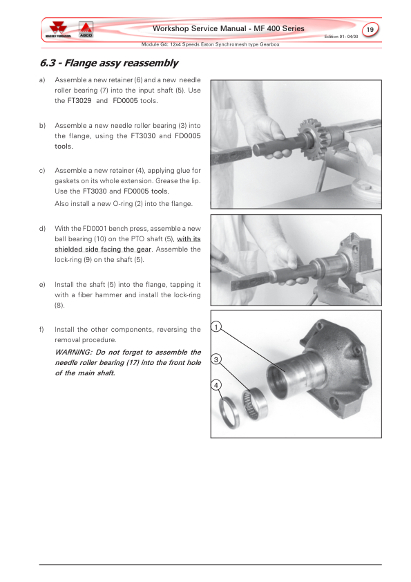
10. 12×4 Constant-Mesh Transmission – Eaton Gearbox
- Eaton 12×4 Transmission Introduction
- Gearbox Component Identification
- Eaton 12×4 Transmission Power Flow
- Transmission Gear Diagrams
- Gearbox Removal from Tractor
- Gearbox Mounting on Workshop Service Support
- Footstep Tractor Gear Selector System
- Footstep Tractor Gear Shift Levers and Cover
- Gear Selector Shafts and Forks
- Cab Tractor Gear Selector System
- Cab Tractor Side-Shift Mechanism
- Cab Tractor Gear Shift Levers
- Shift Lever Shafts and Forks
- Transmission Clutch Release Mechanism
- Clutch Mechanism Component Identification
- Clutch Mechanism Removal and Disassembly
- Clutch Mechanism Reassembly
- Slow and Fast Speed Range Assembly
- Speed Range Assembly Removal and Disassembly
- Speed Range Assembly Reassembly
- Front Retainer Flange and Transmission Input Shafts
- Input Shaft Removal and Disassembly
- Front Flange Reassembly
- High and Low Range Axial Clearance Adjustment
- Transmission Mainshaft
- Mainshaft Removal and Disassembly
- Mainshaft Reassembly and Adjustment
- PTO Output Shaft and Lower Layshaft
- PTO Output Shaft Removal and Disassembly
- Layshaft Removal and Reassembly
- Lower High/Low Range Axial Clearance Adjustment
- PTO Output Shaft Reassembly
- Reverse Gear Assembly
- Reverse Gear Removal and Disassembly
- Reverse Gear Reassembly
- Transmission Component Inspection
- Transmission Failure Diagnosis
- Gearbox Bushings, Sleeves and Coupling Sets
- Creeper Gear Maintenance
-
11. 12×4 Partial Synchromesh Transmission – Eaton Gearbox
- Eaton 12×4 Partial Synchromesh Gearbox Introduction
- Gear Shift Component Identification
- Eaton 12×4 Transmission Power Flow
- Transmission Gear Diagrams
- Gearbox Removal and Service Support
- Transmission Clutch Mechanism
- Clutch Mechanism Component Identification
- Clutch Mechanism Removal and Disassembly
- Clutch Mechanism Reassembly
- Gear Selector Shafts and Forks
- Footstep Tractor Gear Selector Arrangement
- Cab Tractor Side Gear Selector Arrangement
- Fast and Slow Speed Range Assembly
- Speed Range Assembly Removal and Disassembly
- Speed Range Assembly Reassembly
- Front Transmission Flange and Input Shafts
- Front Flange Removal and Disassembly
- Front Flange Reassembly
- High/Low Range Upper Assembly Axial Clearance
- Transmission Mainshaft
- Mainshaft Removal and Disassembly
- Mainshaft Reassembly and Adjustment
- PTO Output Shaft and Lower Layshaft
- PTO Output Shaft Removal and Disassembly
- Layshaft Removal
- Layshaft Reassembly
- High/Low Range Lower Assembly Axial Clearance
- PTO Output Shaft Reassembly
- Reverse Gear Assembly
- Reverse Gear Removal and Disassembly
- Reverse Gear Reassembly
- Transmission Synchromesh Sets
- Synchromesh Component Identification
- Synchromesh Set Reassembly
- Selector Fork Centralisation
- Coupling Ring and Hub Alignment
- Transmission Component Inspection and Fault Diagnosis
- Gearbox Bushing and Sleeve Recommendations
-
12. Rear Axle, Differential and Brakes
- Rear Axle General Description and Operation
- Rear Axle Final Drives
- Final Drive Component Identification
- Final Drive Removal
- Final Drive Disassembly
- Final Drive Component Inspection and Replacement
- Final Drive Reassembly
- Final Drive Bearing Preload Adjustment
- Rear Axle Trumpet Housings
- Rear Axle Trumpet Removal
- Rear Axle Trumpet Reinstallation
- Rear Brake System
- Brake Pedal Free-Travel Inspection and Adjustment
- Rear Brake Discs
- Brake Actuating Rod Protective Boot Replacement
- Rear Brake Reassembly
- Rear Differential
- Differential Lock Mechanism
- Differential Satellite Gear Housing and Ring Gear
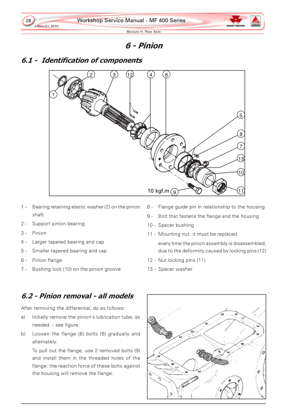
- Rear Drive Pinion
- Pinion Component Identification
- Drive Pinion Removal
- Pinion Assembly Disassembly
- Drive Pinion Component Inspection
- Pinion Assembly Reassembly
- Pinion Bearing Preload Adjustment
- Ring Gear and Pinion Assembly Adjustment
- Differential Bearing Preload Adjustment
- Ring Gear and Pinion Backlash Adjustment
- Ring Gear and Pinion Tooth Contact Inspection
- MF 415 Rear Half-Shaft Without Final Drive
- MF 415 Half-Shaft Component Identification
- MF 415 Rear Half-Shaft Disassembly
- MF 415 Half-Shaft Component Inspection
- MF 415 Half-Shaft Endplay Adjustment
- Rear Axle General Technical Specifications
-
13. Ferguson Hydraulic Lifting System
- Ferguson Hydraulic System Introduction
- Hydraulic System Component Identification
- Ferguson Hydraulic System Operating Principles
- Hydraulic Pump Check Valve Positions
- Ferguson Draft Control System
- Ferguson Position Control System
- Hydraulic System Flow Diagram
- Ferguson Hydraulic Pump
- Hydraulic Pump Removal
- Hydraulic Pump Disassembly
- Hydraulic Pump Component Inspection
- Hydraulic Pump Valve Seat Grinding
- FT5004 Hydraulic Pump Milling Tool Kit
- Ferguson Hydraulic Pump Reassembly
- Hydraulic Pump Reinstallation
- Hydraulic Pump Adjustment
- Hydraulic Lift Cover Assembly
- Hydraulic Lift Cover Removal
- Hydraulic Lift Cover Disassembly
- Hydraulic Lift Cover Component Inspection
- Hydraulic Lift Cover Reassembly
- Hydraulic Lift Cover Internal Adjustments
- Hydraulic Lift Cover Reinstallation
- Hydraulic Lift Cover Final Adjustments
- Outer Hydraulic Cylinders – MF 460 to 475 Reference
- Outer Hydraulic Cylinder Component Identification
- Outer Hydraulic Cylinder Inspection and Reassembly
- Ferguson Hydraulic System Final Assembly
-
14. Power Take-Off – PTO and Independent PTO (IPTO)
- Power Take-Off System Introduction
- Independent Power Take-Off Power Flow
- Engine Speed and PTO Output Shaft Rotation
- PTO and IPTO Maximum Power References
- Independent PTO Assembly Removal
- IPTO Side Cover and Control Valves
- Hydraulic Flow Through the IPTO Side Cover
- IPTO Control Valve Component Identification
- IPTO Control Valve Removal and Disassembly
- IPTO Control Valve Component Inspection
- IPTO Control Valve Reassembly
- Independent PTO Hydraulic Pressure Testing
- PTO Pressure-Maintaining Valve
- Independent PTO Clutch Disc Pack
- Clutch Disc Pack Component Identification
- Clutch Disc Pack Disassembly
- Clutch Disc Pack Inspection
- Clutch Disc Pack Reassembly
- Independent PTO Drive Pump
- IPTO Drive Pump Component Inspection
- IPTO Drive Pump Reassembly
- Dual-Speed PTO and IPTO – 540/1000 RPM
- Dual-Speed PTO Power Flow
- PTO Output Shaft Speed Conversion Procedure
- PTO Speed Selector Gear Train Maintenance
- Independent PTO Reinstallation
- Mechanical Power Take-Off System
- Mechanical PTO General Diagram
- Live PTO Engagement Mechanism
-
15. Electrical System and Wiring Diagrams
- Electrical System General Specifications
- Electrical Circuits for Footstep Tractors
- Electrical Circuits for Cab Tractors
- Electrical Fuse, Relay and Diode Board
- Footstep Tractor Electrical Fuse and Relay Arrangement
- Cab Tractor Electrical Fuse and Relay Arrangement
- Prestolite Alternator
- Prestolite Alternator Disassembly
- Prestolite Alternator Reassembly
- Prestolite Alternator Testing
- Prestolite Starter Motor
- Starter Motor Disassembly
- Starter Motor Component Cleaning and Inspection
- Starter Motor Reassembly
- Starter Motor Testing
- Instrument Panel
- Electrical Relays
- Fuel Level Sender
- Engine Temperature Sensor
- Fuel Injection Pump Solenoid
- Tractor Battery System
-
16. Auxiliary Hydraulic System and Hydrostatic Steering
- Auxiliary Hydraulic System Introduction
- Auxiliary Hydraulic Circuit Diagrams
- Hydraulic System Pressure Testing
- Hydrostatic Steering Pressure Test
- Auxiliary Hydraulic Control Valve Pressure Test
- Danfoss Hydrostatic Steering Unit
- Hydraulic Oil Flow Through the Danfoss Unit
- Danfoss Steering Unit Hydraulic Circuits
- Danfoss Steering Unit Component Identification
- Danfoss Steering Unit Hydraulic Connections
- Danfoss Steering Unit Overhaul Recommendations
- Danfoss Steering Unit Disassembly
- Danfoss Steering Unit Component Inspection
- Danfoss Steering Unit Reassembly
- Auxiliary Hydraulic Control Valve
- Auxiliary Control Valve Component Identification
- Auxiliary Control Valve Hydraulic Circuit
- Auxiliary Hydraulic Pump Assemblies
- Hydraulic Pump Component Identification
- Auxiliary Hydraulic Pump Removal
- Auxiliary Hydraulic Pump Disassembly
- Hydraulic Pump Component Inspection
- Auxiliary Hydraulic Pump Troubleshooting
- Auxiliary Hydraulic Pump Reassembly
- Hydraulic Oil Filtering
- Danfoss Priority Valve – MF 465/475 Reference
- Hydraulic Heat Exchanger – MF 465/475 Reference
Identifying the Correct Engine, Axle and Transmission Service Procedures
The Massey Ferguson MF 400 Series workshop documentation covers several component arrangements rather than one identical specification for every tractor. Engine servicing includes Perkins A3.152, A4.236, P4000 and 1000 Series references, with dedicated information for fuel injection testing, valve clearance adjustment, cylinder compression checks and mechanical specifications. Identify the installed engine before consulting its specifications or carrying out engine adjustments.
Front axle servicing is divided between the conventional two-wheel-drive axle, Carraro 20.14/20.18/20.21 four-wheel-drive axles and ZF/APL 335/345/350 assemblies. These axle families have separate differential, final drive, steering cylinder and bearing adjustment references. The rear axle chapter also identifies a specific MF 415 half-shaft arrangement without a final drive.
The transmission chapters distinguish the 8×2 sliding-gear gearbox from the Eaton 12×4 constant-mesh and partial synchromesh arrangements. The manual also identifies multiple clutch types, including dual-stage, split-torque and heavy-duty configurations. Confirm the fitted gearbox and clutch before selecting dismantling, component inspection or adjustment procedures.
Shared MF 400 Series references: Some hydraulic sections identify additional models, including the MF 460, 465 and 475. These references form part of the broader workshop documentation but do not automatically establish their applicability to MF 415, 425, 435 or 440 tractors. Check the relevant model and component identification before using those procedures.




















Reviews
There are no reviews yet.